Novel chopper circuit for fiber optic gyroscopes

A technology of fiber optic gyroscope and chopper circuit, which is applied in the direction of Sagnac effect gyroscope, gyroscope/steering sensing equipment, instrument, etc., to avoid signal jumps and eliminate spikes and glitches

Active Publication Date: 2019-03-12
CHINA ELECTRONICS TECH GRP NO 26 RES INST
View PDF7 Cites 1 Cited by
  • Summary
  • Abstract
  • Description
  • Claims
  • Application Information

AI Technical Summary

Problems solved by technology

Commonly used chopper circuits will introduce new signal steps while removing sharp pulses

Method used


Image

  • Novel chopper circuit for fiber optic gyroscopes
  • Novel chopper circuit for fiber optic gyroscopes
  • Novel chopper circuit for fiber optic gyroscopes

Examples


Embodiment 1

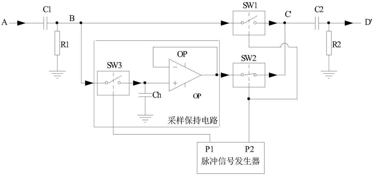
[0025] The present invention proposes a novel chopper circuit for an optical fiber gyroscope, including a first high-pass filter, a sample-and-hold circuit, a pulse signal generator, a first analog switch, a second analog switch, and a second high-pass filter; The above circuit chops the sharp pulse through the analog switch under pulse control, and at the same time samples and holds the effective signal. Finally, through the combination of each analog switch, the removal of the spike interference signal is realized and the effective signal is 0 bias. place.

[0026] The process that novel chopper circuit of the present invention realizes peak pulse removal can comprise as follows:

[0027] 1) The modulated signal output by the detector passes through the first high-pass filter to eliminate most of the zero offset;

[0028] 2) The signal filtered in the first step is respectively sent to the first analog switch and the sample-and-hold circuit, and the sample-and-hold circuit ...

Embodiment 2

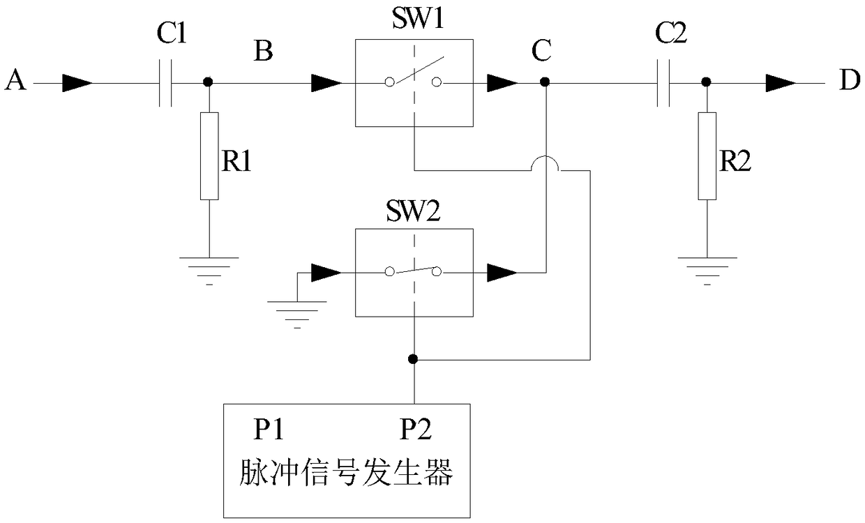
[0031] The present embodiment further describes the novel chopper circuit of the present invention in conjunction with specific data; the present invention can be used to remove spike pulses in the output signal of the fiber optic gyroscope detector; the present invention mainly includes four parts: the first high-pass filter, Chopping process, sampling and holding, and a second high-pass filter; the novel chopping circuit includes a first high-pass filter, a sampling and holding circuit, a pulse signal generator, a first analog switch, a second analog switch, and a second high-pass filter; like figure 1 shown.

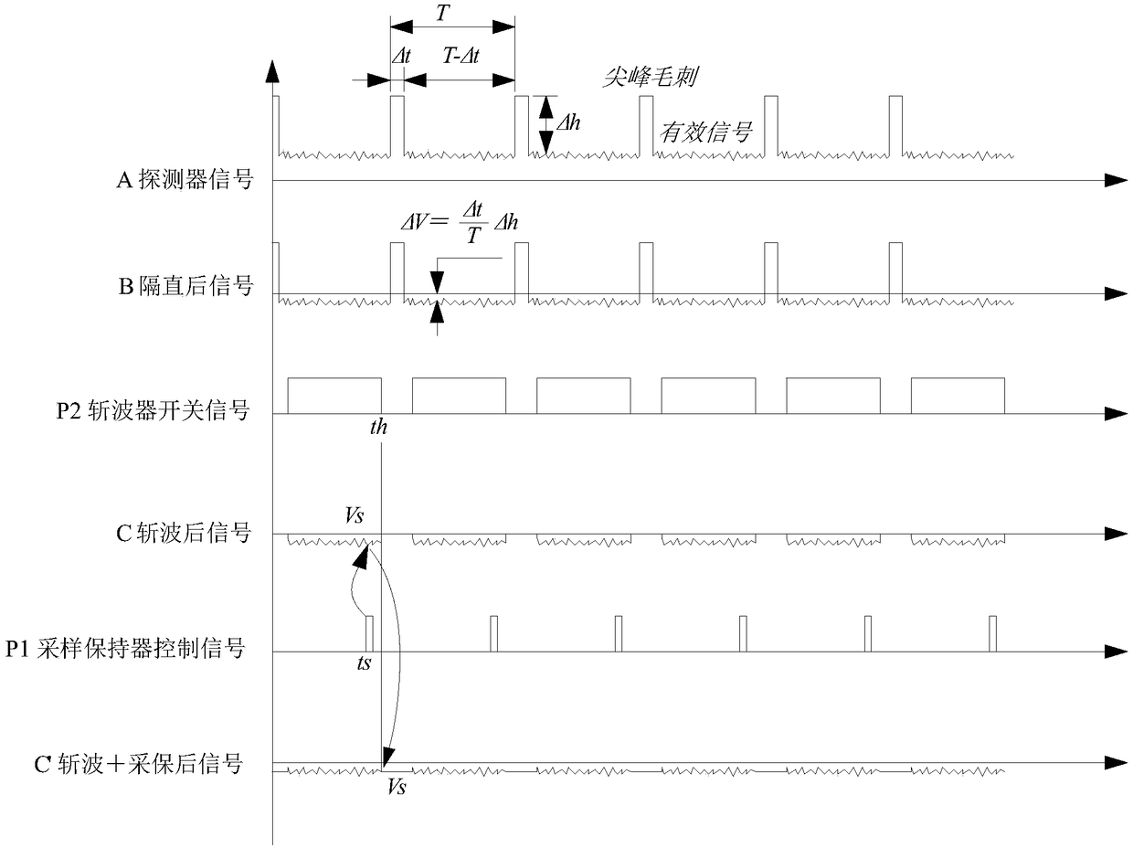
[0032] Point A is the output signal of the detector, that is, the input signal of the circuit, and its signal schematic diagram is as follows image 3 shown. image 3 The useful signal is expressed as a curve with noise fluctuations, and the spike interference signal is expressed as an ideal rectangular square wave.

[0033] The first high-pass filtering part of th...


PUM


Abstract

The invention belongs to the field of fiber optic gyroscopes, and particularly relates to a novel chopper circuit for the fiber optic gyroscopes. The novel chopper circuit comprises a first high-passfilter, a sampling hold circuit, a pulse signal generator, a first analog switch, a second analog switch and a second high-pass filter; the output end of the first high-pass filter is connected with the first analog switch and the sampling hold circuit, and the output end of the sampling hold circuit is connected with the second analog switch; the pulse signal generator sends pulse signals to thesampling hold circuit, the first analog switch and the second analog switch; and the second high-pass filter receives signals from the first analog switch and the second analog switch. The novel chopper circuit is provided for the digital closed-loop fiber optic gyroscopes, peak glitches can be eliminated completely, the signals are straight without steps, the mean value is zero, and a subsequentcircuit is subjected to signal processing very advantageously; and the whole circuit is simple in composition and high in reliability.

Description

technical field [0001] The invention relates to an improvement of a chopping circuit in a fiber optic gyroscope, which is used for removing spike pulse interference in a detector output signal, and belongs to the field of fiber optic gyroscopes; in particular, it is a novel chopping circuit for a fiber optic gyroscope. Background technique [0002] The fiber optic gyroscope is a new type of all-solid-state inertial instrument that utilizes the Sagnac effect to sense the rotation angle or the rotation angular rate. , simple production process and many other advantages, it is widely used in aviation, aerospace, navigation, ground weapon systems and industrial fields, and is one of the most widely used new gyroscopes at present. [0003] The fiber optic gyroscope is composed of two parts, the optical path and the circuit. The optical path is mainly composed of a light source, a Y waveguide, and a detector to form a Sagnac interferometer. The circuit part realizes the functions...

Claims


Application Information

Patent Timeline
Patent Type & Authority Applications(China)
IPC IPC(8): G01C19/72
CPCG01C19/721
Inventor 雷霆陈朝春周昌学卜继军
Owner CHINA ELECTRONICS TECH GRP NO 26 RES INST
Why Eureka
Try Eureka