
On-line calibration method of thermal imager in space simulation environment

A technology for simulating the environment and thermal imagers, which is applied to instruments, scientific instruments, radiation pyrometry, etc. It can solve the problems of low temperature of the standard plate, great influence, and large measurement errors, etc., and achieves strong environmental adaptability and measurement Small error and good uniformity

Active Publication Date: 2019-08-23
BEIJING AEROSPACE INST OF THE LONG MARCH VEHICLE
View PDF1 Cites 0 Cited by
  • Summary
  • Abstract
  • Description
  • Claims
  • Application Information

AI Technical Summary

Problems solved by technology

At present, regarding the calibration equipment, the domestic calibration devices in the vacuum and low temperature environment in the past are generally installed in a fixed position for calibration of a specific equipment, or multiple measuring devices are moved to the fixed position for calibration before the test. However, it is impossible to calibrate multiple measuring devices at the same time without changing the measurement optical path during one test, let alone take into account the internal and external calibration of the container at the same time, and most of the devices do not have the ability to calibrate at low temperatures below -100 ° C, or have low temperature High temperature calibration above 100℃ cannot be taken into account
[0004] And the traditional method of off-line calibration before and after the test, the error is also very large
At present, there are two ways to arrange the thermal imager for target radiation measurement. One is to arrange it outside the space simulation container and observe the target through the window on the tank wall. Due to the self-radiation of the window glass and the reflection of the environment, it causes a lot Large measurement error, even if the device is calibrated with an external blackbody, the influence of the window cannot be eliminated, especially for the measurement of low temperature targets, this influence is already greater than the target radiation amount
In the second case, the equipment is calibrated outside the tank before and after the test, and then the measuring equipment is placed in a space simulation container. Since the equipment is in a vacuum and cold environment during the measurement process, the working temperature of the equipment is much lower than the temperature during calibration , and the working temperature has a great influence on the measurement results, so it will cause a large measurement error
[0005] In addition, the non-uniformity correction of the thermal imager image usually adopts the method of self-contained standard plate or external standard plate, but the temperature of the standard plate in the vacuum and low temperature environment is very low, even lower than the measurable temperature of the thermal imager, which can no longer be used Non-Uniformity Correction
[0006] In short, the failure of measuring equipment in a specific environment and the inaccurate data collection caused by environmental changes are the current problems

Method used


Image

  • On-line calibration method of thermal imager in space simulation environment
  • On-line calibration method of thermal imager in space simulation environment
  • On-line calibration method of thermal imager in space simulation environment

Examples


Embodiment Construction

[0035] The characteristics and exemplary embodiments of various aspects of the present invention will be described in detail below. In order to make the purpose, technical solutions and advantages of the present invention more clear, the detailed description will be described below in conjunction with the accompanying drawings and embodiments. It should be understood that the described specific embodiments are only regarded as explaining the present invention, not as limiting the present invention. It will be apparent to one skilled in the art that the present invention may be practiced without some of these specific details.

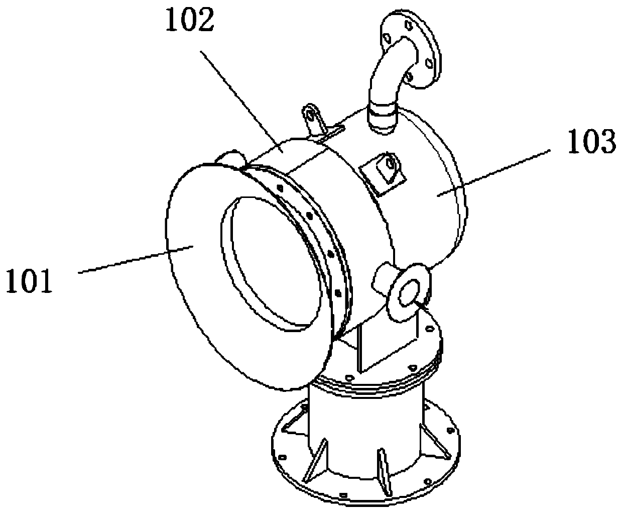
[0036] The invention provides an online calibration method for a thermal imager in a space target infrared radiation simulation test. In the method, a blackbody is used as a calibration device. Such as figure 1 As shown, the main structure of the blackbody is a variable temperature source, which is composed of a radiator 101, a temperature regulating b...


PUM


Abstract

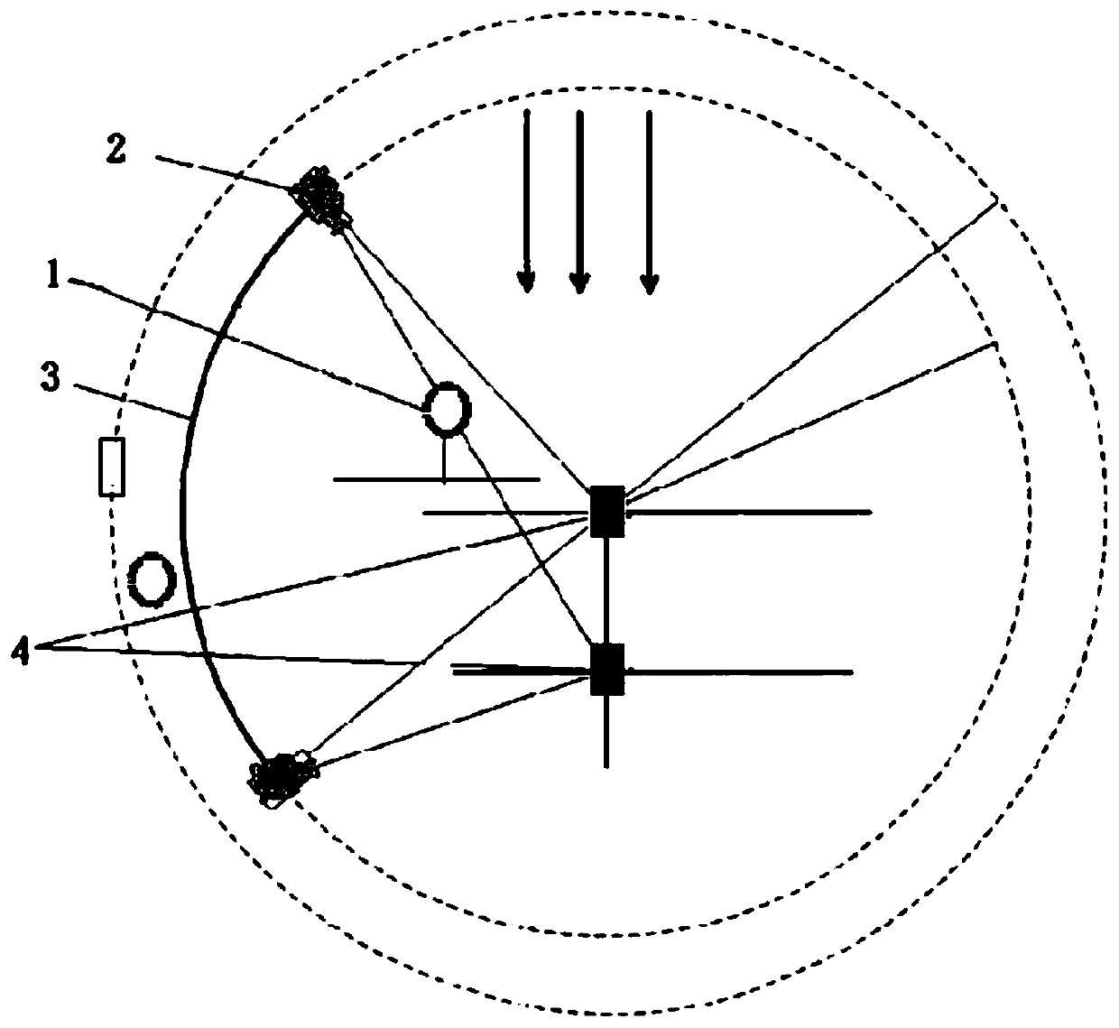
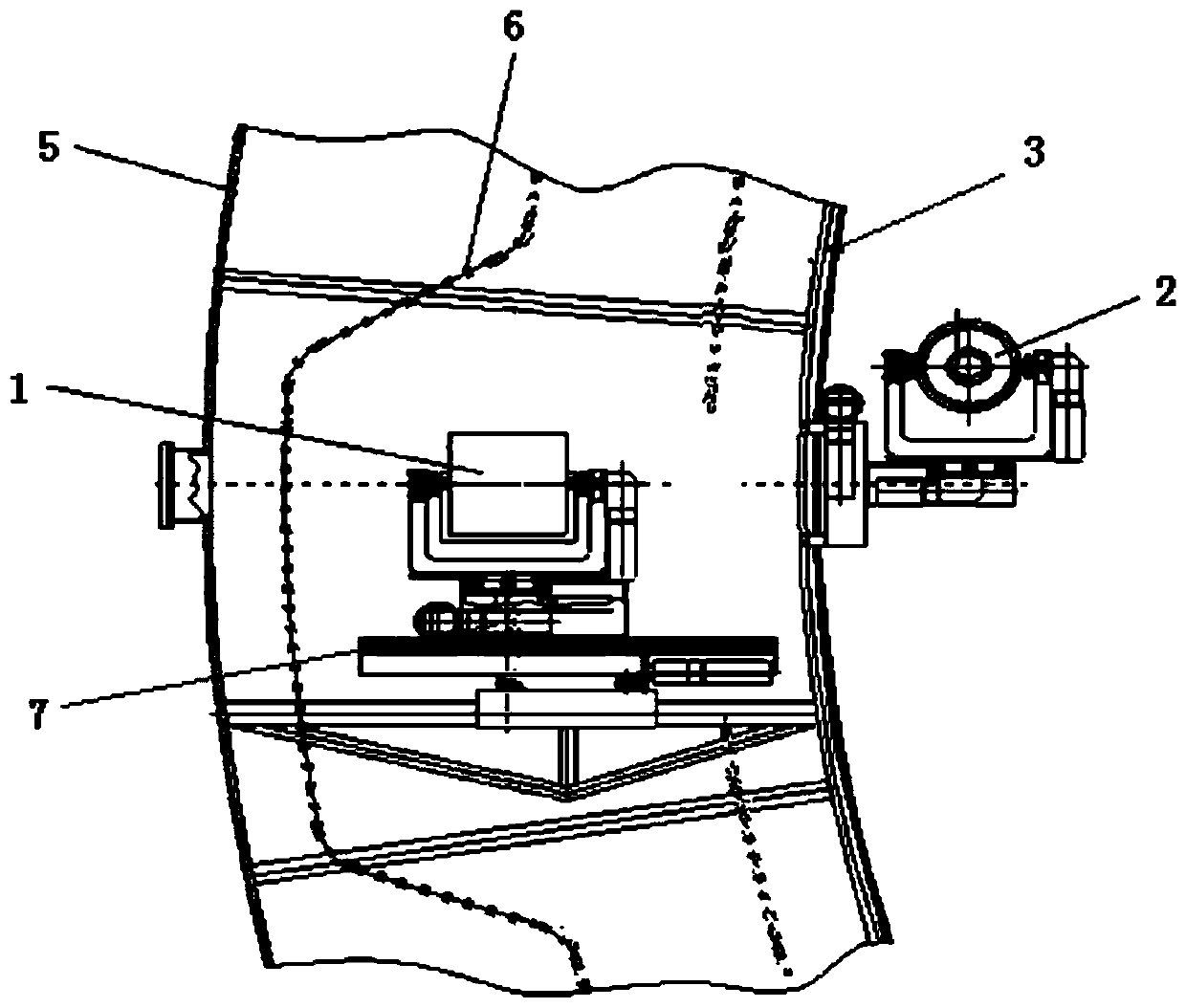
The invention relates to an online calibration method of a thermal imager in a space simulation environment. A space simulation container is set, and a black body is placed as a calibration device in the interlayer between the inner wall of the space simulation container and a heat sink, and / or inside the space simulation container. The test target is also placed in the space simulation container, the thermal imager is placed outside or inside the space simulation container, the relative position between the thermal imager and the blackbody is adjustable, and the thermal imager is calibrated online in real time by collecting images of the blackbody. The invention can move in and out of the calibration device flexibly in one test, can realize the calibration of the thermal imager inside or outside and the measurement of the target in the same test field, and the measurement error is small.

Description

technical field [0001] The invention relates to a space target ground test technology, in particular to a real-time online calibration method for a thermal imager in a space target ground simulation test. Background technique [0002] The ground environment simulation test of space targets is a long-term process. When the infrared thermal imaging camera is tested in this environment, one calibration often cannot meet the accuracy requirements. [0003] Therefore, it is necessary to equip the infrared measurement equipment with a radiation calibration device when carrying out the ground optical characteristic measurement test. At present, regarding the calibration equipment, the domestic calibration devices in the vacuum and low temperature environment in the past are generally installed in a fixed position for calibration of a specific equipment, or multiple measuring devices are moved to the fixed position for calibration before the test. However, it is impossible to calib...

Claims


Application Information

Patent Timeline
Patent Type & Authority Patents(China)
IPC IPC(8): G01J5/52
CPCG01J5/80G01J5/53
Inventor 孟刚薛莲南华周岩范小礼邓蓉李亚男蔡雯琳毛嵩程李志峰水涌涛刘佳琪高路刘成国刘得成赵民
Owner BEIJING AEROSPACE INST OF THE LONG MARCH VEHICLE
Learn More