Supercharge Your Innovation With Domain-Expert AI Agents!

A conduction test device

A conduction test and conduction technology, applied in the direction of electrical connection test, etc., can solve the problems of taking up a lot of manpower and operating time, increasing error factors, and low detection efficiency, so as to improve test efficiency and accuracy, improve efficiency and correctness , The effect of ensuring reliability

Active Publication Date: 2020-09-08
SUZHOU HUAZHAN SPACE APPLIANCE
View PDF6 Cites 1 Cited by
  • Summary
  • Abstract
  • Description
  • Claims
  • Application Information

AI Technical Summary

Problems solved by technology

[0003] Traditional test methods, such as multimeters or buzzer test tools to achieve point-to-point continuity testing, require a lot of manpower and operating time; when encountering connectors with dense pins or mass-produced connectors, one person is required to assist in testing, and it is easy Temporary fatigue and dizziness of the tester's eyes, and low detection efficiency
In addition, the conduction confusion of adjacent pins caused by human factors such as improper operation by the tester increases unnecessary error factors and greatly reduces the accuracy and efficiency of the test.

Method used


Image

  • A conduction test device
  • A conduction test device
  • A conduction test device

Examples


Embodiment 1

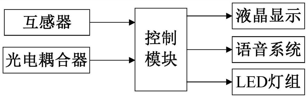
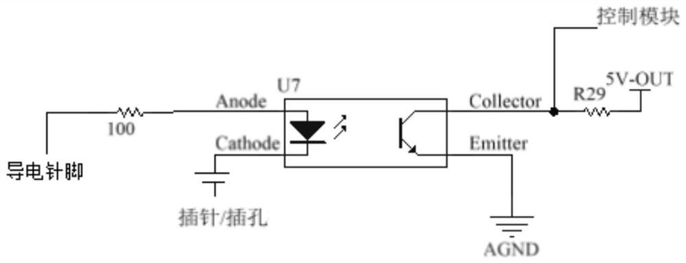
[0034] In this embodiment, the number of photocouplers is the same as the number of connector contact components, refer to image 3 As shown, a test loop is formed between the input terminal of an optocoupler, a voltage source, and a connector contact component, and a pin / hole at both ends of the tested connector. If there is conduction between the pins / holes, the test circuit is conducted, and the output terminal of the photocoupler sends a conduction signal to the control module.

[0035] A current transformer (not shown) is provided on the first wire or the second wire, and the signal output end of the current transformer is connected to the control module. Since the number of pins / holes connected to the connector contact assembly is in multiples of the current, the output signal of each current transformer can be used to judge the current flowing on the wire, and then the current value detected by each current transformer can be compared. It is judged whether each connect...

Embodiment 2

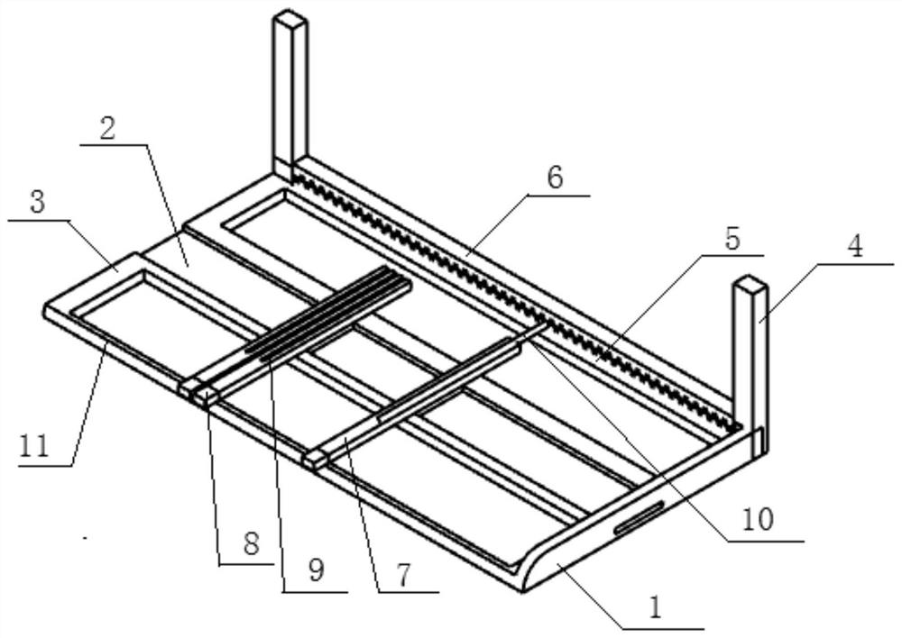
[0045] Based on the conduction test device of embodiment 1, when the connector to be tested is tested, the distance between the connector contact components can be adjusted according to the model specifications or the actual distance between the pins / holes of the connector to be tested, and then by The positioning fixture fixes the conductive pins in the holding holes, thereby fixing the position of the contact components of each connector, and the conductive pins are reliably connected to the conductive ends of the connector contact components, and at the same time, the pins / holes at one end of the connector to be tested are respectively docked A connector contacts the conductive end of the assembly.

[0046] The input end of each photocoupler is used to connect a pin / hole at one end of the electrical connector under test and a conductive pin of a connector contact assembly, so that when the corresponding pin / hole of the connector under test is turned on, a The loop is turned...


PUM


Abstract

The invention discloses a conducting test device, which comprises a conducting test frame, a connector contact assembly, a control module, a photoelectric coupler and a conducting result output module. A plurality of connector contact assemblies are arranged on the conducting test frame in a mutually parallel sliding way; one end of each connector contact assembly is a conductive end for electrically connecting a contact pin / jack at one end of the connector to be tested, and the other end is provided with a conductive pin electrically connected with the conductive end; one end of the input endof the photoelectric coupler is electrically connected with the conductive pin through a lead, and the other end of the input end of the photoelectric coupler is connected with the contact pin / jack at the other end of the connector to be tested after passing through a power supply through the lead; the control module judges whether the two ends of the input end of the corresponding photoelectriccoupler are conducted or not according to the output signal of the photoelectric coupler, further judges whether the contact pins / jacks at the two ends of the corresponding electric connector to be tested are conducted or not, and then outputs the corresponding conduction judgment result. The conducting test device can adapt to the conduction test of various types of connectors and improve the test efficiency and the test precision.

Description

technical field [0001] The invention relates to the technical field of connector performance detection, in particular to a continuity test device. Background technique [0002] During the production process of connectors, it is necessary to conduct electrical performance tests on their sockets and plugs. Nowadays, the development trend of connectors focuses on miniaturization, compactness and convenience, such as I / O socket pin spacing: 2mm×2mm, 1.524mm×1.778mm, 2.54mm×2.54mm, 1.25mm×1.25mm, 3.96mm×3.96mm, 5.08mm×5.08mm, 4.2mm×4.2mm. Therefore, the conduction detection standards for the pins of electronic products are becoming more and more stringent, and the technical requirements are getting higher and higher. [0003] Traditional test methods, such as multimeters or buzzer test tools to achieve point-to-point continuity testing, require a lot of manpower and operating time; when encountering connectors with dense pins or mass-produced connectors, one person is required ...

Claims


Application Information

Patent Timeline
Patent Type & Authority Patents(China)
IPC IPC(8): G01R31/69
CPCG01R31/69
Inventor 赵剑
Owner SUZHOU HUAZHAN SPACE APPLIANCE
Features
  • R&D
  • Intellectual Property
  • Life Sciences
  • Materials
  • Tech Scout
  • Unparalleled Data Quality
  • Higher Quality Content
  • 60% Fewer Hallucinations
Learn More