Backlight driving method and device and liquid crystal display device

A technology of backlight drive and optical drive module, which is applied in the field of backlight drive methods, liquid crystal display devices, and devices, can solve problems such as increasing the complexity of backlight drive design, wasting manpower, and material resources, and achieves improved portability, simple method, Avoid the effects of heavy calculations

Active Publication Date: 2019-03-12
BOE TECH GRP CO LTD +1
View PDF11 Cites 7 Cited by
  • Summary
  • Abstract
  • Description
  • Claims
  • Application Information

AI Technical Summary

Problems solved by technology

[0005] The delay calculation of thousands of backlight drive channels increases the design complexity of the backlight drive. Once the partition is increased or decreased, or the layout of the partitions is changed, the delay data of all the backlight drive channels needs to be recalculated, resulting in different sizes of LCD panels. A large number of repeated designs, wasting manpower and material resources

Method used


Image

  • Backlight driving method and device and liquid crystal display device
  • Backlight driving method and device and liquid crystal display device
  • Backlight driving method and device and liquid crystal display device

Examples


Embodiment 1

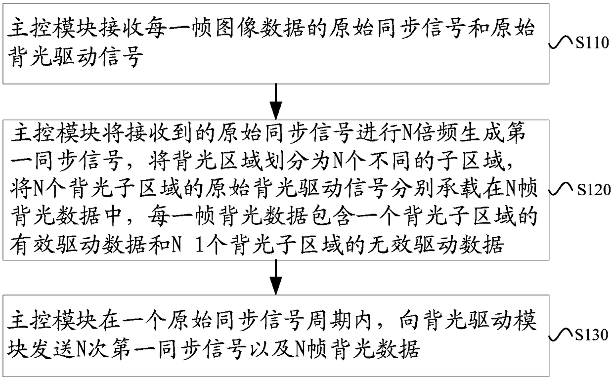
[0020] Such as figure 1 As shown, the embodiment of the present invention provides a backlight driving method, including:

[0021] Step S110: the main control module receives the original synchronization signal and the original backlight driving signal of each frame of image data;

[0022] Step S120: The main control module multiplies the received original synchronization signal by N to generate the first synchronization signal, divides the backlight area into N different sub-areas, and carries the original backlight driving signals of the N backlight sub-areas in N In the frame of backlight data, each frame of backlight data includes valid driving data of one backlight sub-region and invalid driving data of N-1 backlight sub-regions;

[0023] Step S130, the main control module sends the first synchronization signal and N frames of backlight data to the backlight driving module N times within one cycle of the original synchronization signal;

[0024] In the above embodiment,...

Embodiment 2

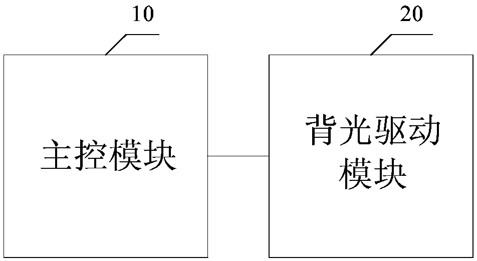
[0029] Such as figure 2 As shown, the embodiment of the present invention provides a backlight driving device, including:

[0030] The main control module 10 is used to receive the original synchronous signal and the original backlight driving signal of each frame of image data; the received original synchronous signal is frequency-multiplied by N to generate the first synchronous signal, and the backlight area is divided into N different sub- region, the original backlight driving signals of N backlight sub-regions are respectively carried in N frames of backlight data, and each frame of backlight data includes valid driving data of one backlight sub-region and invalid driving data of N-1 backlight sub-regions; Send the first synchronization signal N times and N frames of backlight data to the backlight drive module within one original synchronization signal period;

[0031] The backlight driving module 20 is configured to receive a first synchronization signal and backligh...

Embodiment 3

[0036] Such as image 3 As shown, the embodiment of the present invention provides a liquid crystal display device, including the backlight driving device in the above-mentioned embodiment 2.


PUM


Abstract

The invention discloses a backlight driving method. The backlight driving method includes the steps that a main control module receives an original synchronous signal and an original backlight drivingsignal of each frame of image data; the main control module conducts N times of frequency doubling on the original synchronous signal to generate a first synchronous signal, a backlight region is divided into N different sub-regions, original backlight driving signals of the N backlight sub-regions are borne in N frames of backlight data, and each frame of backlight data includes effective driving data of one backlight sub-region and ineffective driving data of N-1 backlight sub-regions; the main control module sends the first synchronous signal and the N frames of backlight data N times to abacklight driving module within one original synchronous signal period. In the technical scheme, a backlight driving scheme which is simple in design and easy to use generally among liquid crystal panels with different dimensions is provided, so that synchronization of liquid crystal displaying and backlight driving is realized.

Description

technical field [0001] The present invention relates to the field of display technology, in particular to a backlight driving method, device and liquid crystal display device. Background technique [0002] With the development of the liquid crystal display panel manufacturing industry, high-resolution AR (Augmented Reality, augmented reality technology) / VR (Virtual Reality, virtual reality) / TV (television) / MNT (monitor) has an impact on MPRT (Motion Picture Response Time, dynamic picture Response time) requirements are becoming more and more stringent. [0003] By adopting Mini LED (submillimeter light-emitting diode) technology, finer backlight adjustment can be achieved, resulting in lower MPRT. There are a large number of Mini LED light sources, which can be divided into thousands of partitions for partition control. However, the output channels of traditional backlight driver chips are generally 16 channels, and a large number of backlight driver chips are needed to re...

Claims


Application Information

Patent Timeline
Patent Type & Authority Applications(China)
IPC IPC(8): G09G3/34
CPCG09G3/3406
Inventor 陈相逸谷其兵刘蕊孙伟
Owner BOE TECH GRP CO LTD
Why Eureka
Try Eureka