Robot joint variable stiffness module capable of locally linearly adjusting stiffness value

A robot joint and manual adjustment technology, applied in the field of robots, can solve the problems of large volume and small rigidity adjustment range of variable rigidity rotating flexible joints, and achieve the effect of realizing flexible drive output, large rigidity adjustment range and reducing overall size.

Pending Publication Date: 2019-03-15
GUANGDONG UNIV OF TECH
View PDF0 Cites 7 Cited by
  • Summary
  • Abstract
  • Description
  • Claims
  • Application Information

AI Technical Summary

Problems solved by technology

However, there is no stiffness amplification structure, resulting in a small stiffness adjustment range, and the u

Method used


Image

  • Robot joint variable stiffness module capable of locally linearly adjusting stiffness value
  • Robot joint variable stiffness module capable of locally linearly adjusting stiffness value
  • Robot joint variable stiffness module capable of locally linearly adjusting stiffness value

Examples


Embodiment 1

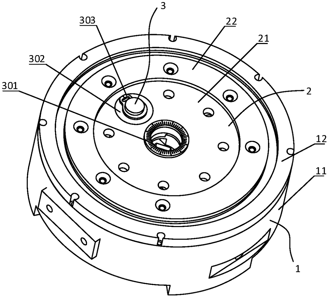
[0034] Such as Figure 1 to Figure 5 As shown, this embodiment discloses a robot joint variable stiffness module that can manually adjust the stiffness locally linearly. The variable stiffness module mainly includes an input part 1 , an output part 2 , and a stiffness adjustment part 3 . A bearing 4 is provided between the input part 1 and the output part 2 to bear the non-torque load of the whole module and make the input part 1 and the output part 2 relatively rotatable.

[0035] Specifically, the input part 1 includes a base 11 and a base bearing retaining ring 12 , the base bearing retaining ring 12 is connected to the base 11 by bolts, and is fixed with the outer ring of the bearing 4 . The base 11 is provided with necessary installation holes and lightening structures. The base 11 is also provided with a guide groove for constraining the large slider 307 and the roller 315 .

[0036] Specifically, the output part 2 includes an output disk 21 and an output disk bearing re...

Embodiment 2

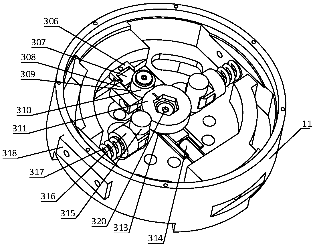
[0044] This embodiment discloses a robot joint variable stiffness module that can manually adjust the stiffness value locally linearly, including an input part 1 , an output part 2 and a stiffness adjustment part 3 . A bearing 4 is provided between the input part 1 and the output part 2 to bear the non-torque load of the whole module and enable the input part 1 and the output part 2 to rotate relatively. The non-torque load is filtered out through the function of the bearing 4, so as to ensure that only the torque load is loaded into the variable stiffness module. Stiffness adjustment part 3 comprises stage clip 317, cam type lever 305, stiffness adjustment fulcrum 310 and fulcrum adjustment part; One end keeps in contact with the compression spring 317 all the time. When the external load is loaded on the output disk 21 of the variable stiffness module, it will act on the compression spring 317 after passing through the cam lever 305. At this time, the compression spring 317...


PUM


Abstract

The invention discloses a robot joint variable stiffness module capable of locally linearly adjusting a stiffness value, comprising an input part, an output part and a stiffness adjustment part. The invention can adjust the stiffness of the module only by adjusting the position of a lever fulcrum. As the position of the lever fulcrum changes, the force arm ratio of the lever also changes between zero and infinity, and the stiffness value of the module changes between zero and infinity. A bearing is provided between the input part and the output part to withstand non-torque loads and enables the input part and the output part to rotate relative to each other. When the output part of the variable stiffness module is subjected to an external transient load, the load is transferred by a cam lever and absorbed by a compression spring, thereby reducing external impact, achieving flexible drive output, and improving the robustness and operational stability of the robot. The invention has theadvantages of compact structure, low cost and linear adjustment within a specified range, so that the invention can be conveniently applied to various interactive devices, especially flexible robot joints.

Description

technical field [0001] The invention relates to the field of robots, in particular to a robot joint variable stiffness module which can manually adjust the stiffness value locally linearly. Background technique [0002] With the rapid development of modern industrial technology, the scope of application of robots has expanded dramatically, and human-machine collaboration has become increasingly close. With the continuous deepening of human-computer interaction, the working environment of the robot has become complex and has great uncertainty. It may collide with objects and people in the surrounding environment at any time, which poses a high challenge to the safety of the robot. Require. For example, the robot needs to dynamically adjust the joint stiffness and the active / passive flexibility of the robot joint according to the changes of the external environment and its own load. Therefore, it has become a technical difficulty in the field of collaborative robots to add a...

Claims


Application Information

Patent Timeline
IPC IPC(8): B25J17/02
CPCB25J17/0241
Inventor 朱海飞赵波钟玉谷世超管贻生
Owner GUANGDONG UNIV OF TECH
Why Eureka
Try Eureka