
Mold closing mechanism of injection molding machine

A mold clamping mechanism and injection molding machine technology, applied in the field of injection molding machines, can solve the problems of high processing cost, insufficient compactness, and high oil cylinder cost, and achieve the effects of stable and accurate motion, oil cylinder cost saving, and compact mechanism

Pending Publication Date: 2019-03-15
HAITIAN PLASTICS MACHINERY GRP
View PDF0 Cites 1 Cited by
  • Summary
  • Abstract
  • Description
  • Claims
  • Application Information

AI Technical Summary

Problems solved by technology

[0003] The above two mold clamping mechanisms are rarely used in micro-miniature injection molding machines with a clamping force less than 60KN. The main reason is that the toggle-type mold clamping mechanism has many parts. The overall length of the toggle-type mold clamping mechanism is long and not compact enough; although the existing two-platen mold clamping mechanism is compact in structure compared with the toggle-type mold clamping mechanism, the clamping cylinder and the cylinder for opening and closing the mold are set independently. The cost of applying the existing two-plate mold clamping mechanism oil cylinder in the micro-small injection molding machine is high

Method used


Image

  • Mold closing mechanism of injection molding machine
  • Mold closing mechanism of injection molding machine
  • Mold closing mechanism of injection molding machine

Examples


Embodiment 1

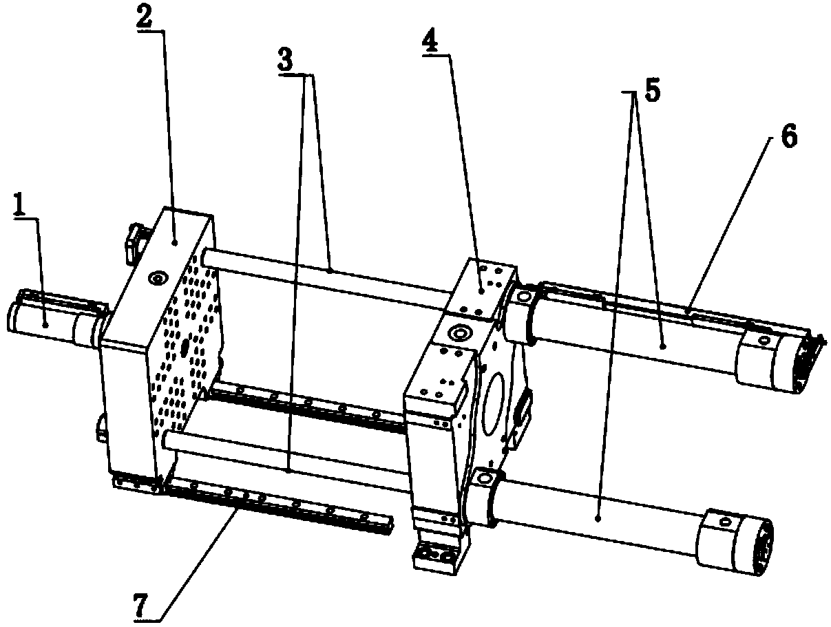
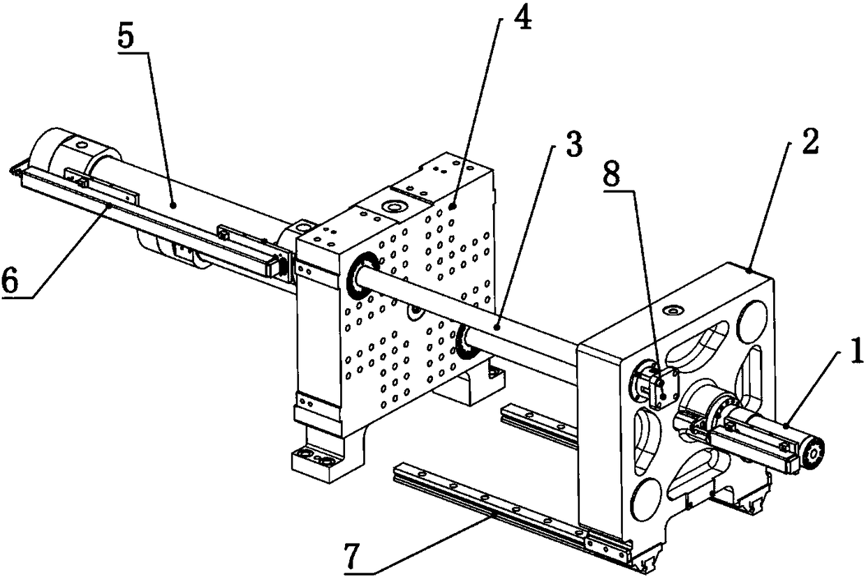
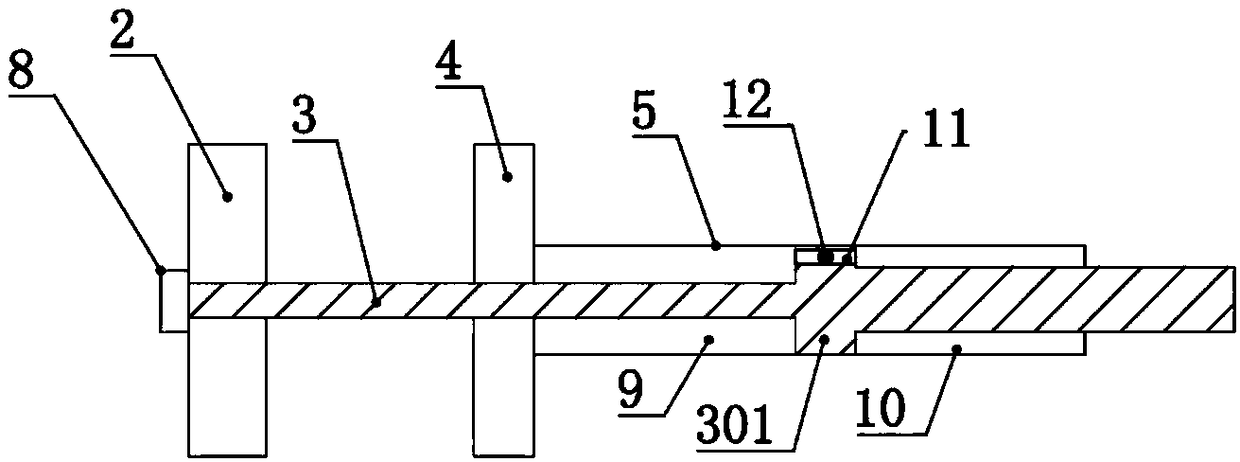
[0033] Provide an injection molding machine mold clamping mechanism, such as Figure 1-Figure 2 As shown, the fixed template 4 and the movable template 2 arranged at parallel intervals are included, and the clamping cylinder 5 is arranged at the end of the fixed template 4 away from the movable template 2, and the clamping cylinder 5 can be arranged in parallel at the diagonally opposite corner of the fixed template 4 Two groups or four groups are arranged symmetrically at the four corners of the fixed template 4. Based on cost considerations, it is preferable to arrange two groups of clamping cylinders 5 obliquely. Through the fixed template 4 and the movable template 2 arranged in parallel, a locking stud is set on the tie rod 3 at the end of the movable template 2 away from the fixed template 4 to fix the tie rod 3 and the movable template 2, and at the joint between the tie rod 3 and the fixed template 4 A lubricating guide sleeve is provided, and the lubricating guide slee...

Embodiment 2

[0037] In this embodiment, on the basis of Embodiment 1, a locking mechanism is added to increase the overall mold locking capability.

[0038] Such as Figure 4-Figure 5 As shown, a second through hole 401 is provided at the other two opposite corners of the movable platen 2 where the clamping cylinder 5 is not provided. Between the fixed platen 4 and the second through hole 401, there is a piston The expansion and contraction of the rod acts as a guide rod 13 that moves telescopically relative to the second through hole 401. A locking mechanism that limits the radial movement of the guide rod 13 is provided on the side of the movable template 2 away from the fixed template 4. The drive mechanism on the midpoint of the line connecting the centers of the two guide rods 13 and the clamping module that clamps the guide rod 13 under the drive of the drive mechanism, the drive mechanism is two locking cylinders 14 facing away from each other, and the locking cylinder 14 The pisto...


PUM


Abstract

The invention discloses a mold closing mechanism of an injection molding machine, which comprises a fixed mold plate and a movable mold plate which are arranged in parallel at intervals, wherein moldlocking oil cylinders are arranged at the end, far away from the movable mold plate, of the fixed mold plate, a cavity A is arranged at the end, close to the fixed mold plate, of a piston of each moldlocking oil cylinder, a cavity B is arranged at the end, far away from the fixed mold plate, of the piston of each mold locking oil cylinder, piston rods are arranged in the cavities A and the cavities B, the diameter of the piston rod of each cavity A is smaller than that of the piston rod of the corresponding B cavity, and two ends of each piston are provided with first through holes for enabling the corresponding cavity A and the corresponding cavity B to communicate with each other are arranged at, each first through hole is internally provided with a control valve capable of opening or closing the first through hole, a pull rod is arranged at the end, far away from the corresponding piston, of the piston rod of each cavity A, the pull rods sequentially penetrate through the fixed mold plate and the movable mold plate, and fastening screws are arranged between the pull rod parts at the end, far away from the fixed mold plate, of the movable mold plate and the movable mold plate. Compared with a toggle rod type mold closing mechanism, the mold closing mechanism of the injection molding machine has the advantages of few parts, simple arrangement, low processing cost and compactstructure, and compared with a two-plate-type mold closing mechanism, the mold closing mechanism has the advantages that the number of oil cylinders is small, and equipment cost is saved.

Description

technical field [0001] The invention relates to the field of injection molding machines, more specifically, it relates to a mold clamping mechanism of an injection molding machine. Background technique [0002] With the development of the plastics industry, injection molding machines are widely used. The mold clamping mechanism is an important part of the injection molding machine, and the entire cycle is mainly composed of mold opening, mold clamping, mold locking, mold breaking, and ejection. At present, the mainstream mold clamping mechanism on the market is divided into toggle type mold clamping mechanism and two-platen mold clamping mechanism. The overall rigidity of the two-platen mold clamping mechanism is good, the structure is simple, and the clamping force is controllable. It is widely used in injection molding machines; small injection molding machines with a clamping force of 60KN-250KN mainly use toggle-type mold clamping mechanisms. [0003] The above two mol...

Claims


Application Information

Patent Timeline
Patent Type & Authority Applications(China)
IPC IPC(8): B29C45/67
CPCB29C45/67
Inventor 陈星欣吴俊胡绘国
Owner HAITIAN PLASTICS MACHINERY GRP
Learn More