
Exhaust gas recirculation device

An exhaust gas recirculation and recirculation technology, applied in exhaust gas recirculation, charging system, machine/engine, etc., can solve problems such as restricting installation space, and achieve the effect of improving cooling efficiency, simplifying layout, and reducing weight

Inactive Publication Date: 2019-03-15
HYUNDAI MOTOR CO LTD +1
View PDF8 Cites 3 Cited by
  • Summary
  • Abstract
  • Description
  • Claims
  • Application Information

AI Technical Summary

Problems solved by technology

[0009] In a conventional EGR device, since the capacity of the EGR cooler has to be increased for effectively cooling the EGR gas, the back pressure, weight, and size must also be increased, but the installation space may be limited

Method used


Image

  • Exhaust gas recirculation device
  • Exhaust gas recirculation device
  • Exhaust gas recirculation device

Examples


Embodiment Construction

[0026] Exemplary embodiments of the present invention will be described in detail below with reference to the accompanying drawings.

[0027] It should be understood that the term "vehicle" or "vehicular" or other similar terms as used herein generally includes motor vehicles such as passenger automobiles including sport utility vehicles (SUVs), buses, trucks, various commercial vehicles, Watercraft including boats, ships, aircraft, etc., and including hybrid vehicles, electric vehicles, plug-in hybrid electric vehicles, hydrogen vehicles, and other alternative fuel vehicles (such as fuels derived from energy sources other than petroleum) . As referred to herein, a hybrid vehicle is a vehicle that has two or more sources of power, such as both gasoline-powered and electric-powered vehicles.

[0028] The terminology used herein is for the purpose of describing particular embodiments only and is not intended to be limiting of the invention. As used herein, the singular forms "...


PUM


Abstract

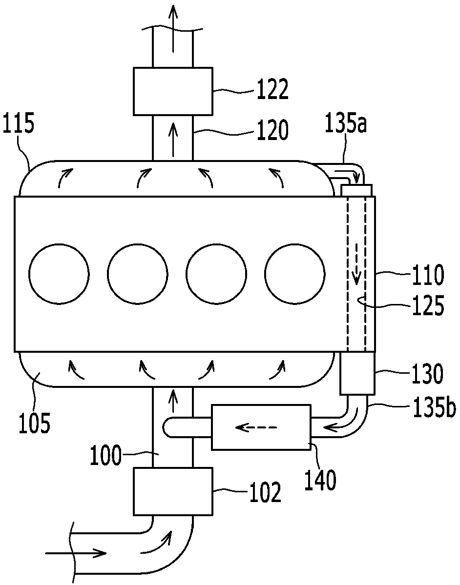
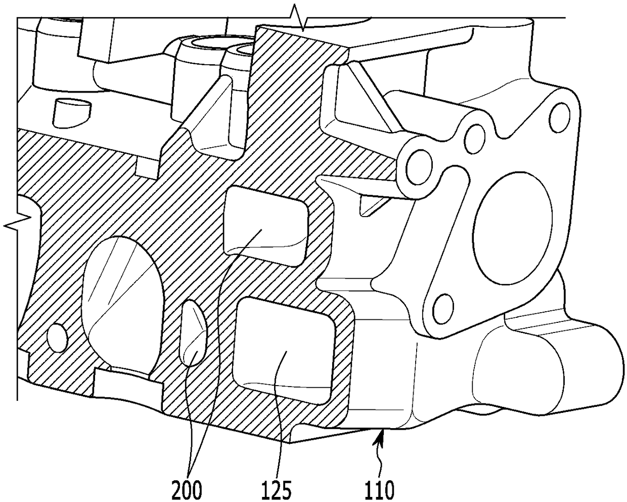
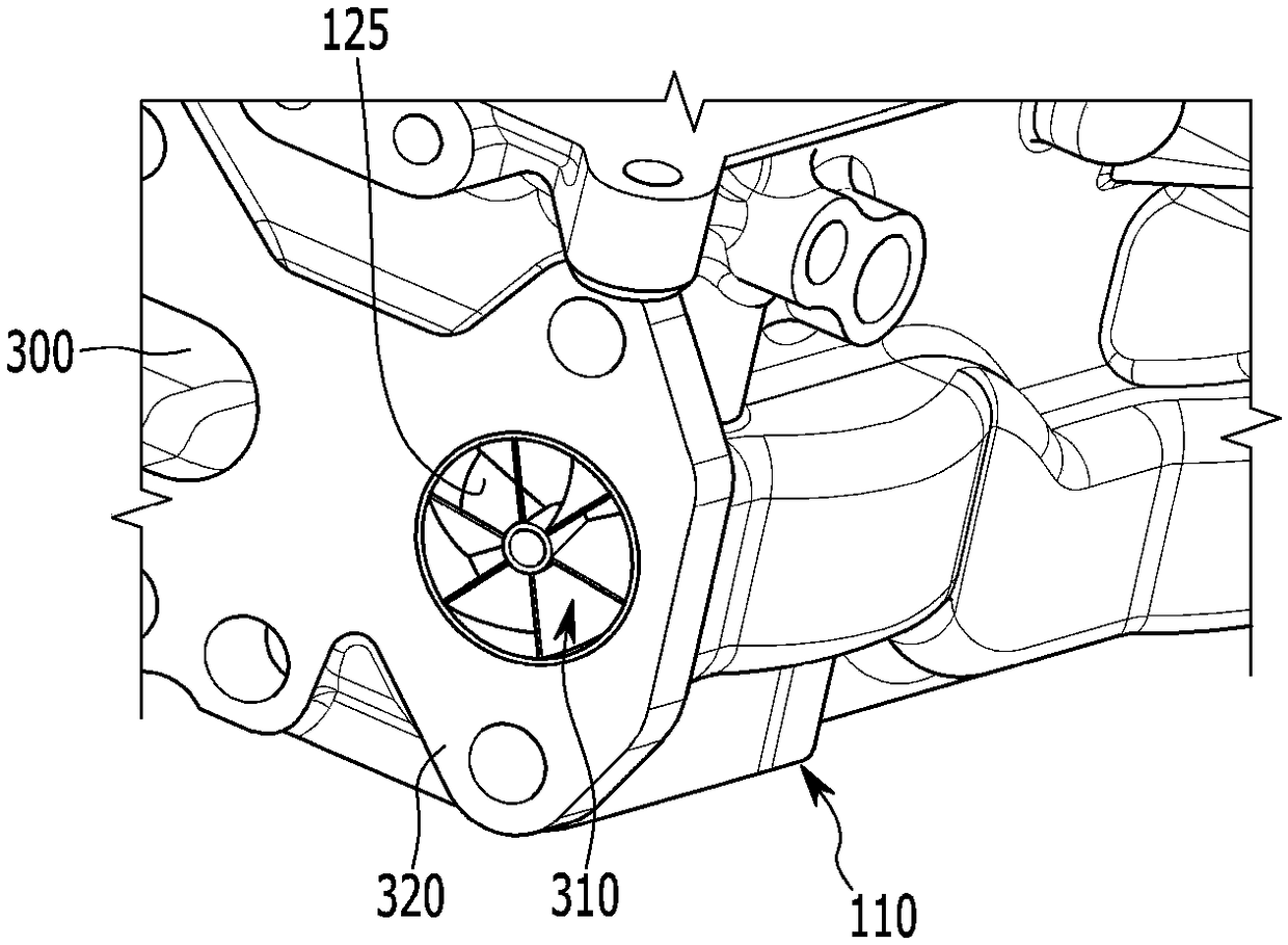
An exhaust gas recirculation (EGR) device includes a cylinder head in which an EGR passage that recirculates EGR gas from an exhaust side to an intake side is formed; a coolant chamber formed inside the cylinder head and at a circumference of the EGR passage, through which coolant cooling the EGR gas passing through the EGR passage passes; and a swirl generator disposed at one side of the EGR passage to form swirl at the EGR gas passing through the EGR passage.

Description

[0001] Cross References to Related Applications [0002] This application claims the benefit of priority from Korean Patent Application No. 10-2017-0114573 filed in the Korean Intellectual Property Office on September 7, 2017, which is hereby incorporated by reference in its entirety. technical field [0003] The present invention relates to an engine, and more particularly, to an exhaust gas recirculation device that recirculates a part of the exhaust gas from the exhaust side to the intake side to lower the temperature of the combustion chamber, thereby reducing the generation of nitrogen oxides and reducing fuel consumption. Background technique [0004] Generally, an EGR (Exhaust Gas Recirculation) device recirculates part of the exhaust gas (hereinafter referred to as "EGR gas") from the exhaust side of the engine to the intake side, and the EGR gas is mixed with external air to be supplied to the combustion chamber. room. [0005] Specifically, when the exhaust gas i...

Claims


Application Information

Patent Timeline
Patent Type & Authority Applications(China)
IPC IPC(8): F02M26/32F02M26/29
CPCF02M26/29F02M26/32F02M26/41F02M26/19F02M26/28F02M26/34F02M26/52F02M2026/001
Inventor 尹圣日李东映朴度俊尹仁圣高昇佑
Owner HYUNDAI MOTOR CO LTD
Learn More