Double-channel simultaneous phase shifting interference microscopic system

A phase-shift interference and microscopy system technology, applied in the field of dual-channel simultaneous phase-shift interference microscopy systems, can solve the problems of insufficient spatial resolution, different spatial relative positions, inconsistent optoelectronic properties, etc., to reduce costs and technical difficulties, The effect of low operation difficulty and high utilization of light energy

Active Publication Date: 2019-03-15
SOUTH CHINA NORMAL UNIVERSITY
View PDF8 Cites 3 Cited by
  • Summary
  • Abstract
  • Description
  • Claims
  • Application Information

AI Technical Summary

Problems solved by technology

[0005] 1. Multiple image sensor systems need to ensure that multiple cameras acquire images synchronously, and the inconsistencies in photoelectric performance and different spatial relative positions of multiple CCDs will have a greater impact on the measurement results;
[0006] 2. Simultaneous collection of multiple phase-shift interferograms in different areas of a single CCD target surface will be limited by many conditions, such as the diffraction direction of the grating is affected by the wavelength, so that this method can only be applied to single-wavelength measurement and cannot be used for white light or narrow-band Light measurement, lack of spatial resolution, special image sensor required, etc.;
[0007] 3. Pixel mask components are difficult to achieve wide commercial applications due to high production costs

Method used


Image

  • Double-channel simultaneous phase shifting interference microscopic system
  • Double-channel simultaneous phase shifting interference microscopic system
  • Double-channel simultaneous phase shifting interference microscopic system

Examples


Embodiment Construction

[0043]The following will clearly and completely describe the technical solutions in the embodiments of the present invention with reference to the accompanying drawings in the embodiments of the present invention. Obviously, the described embodiments are only part of the embodiments of the present invention, not all of them. Based on the embodiments of the present invention, all other embodiments obtained by persons of ordinary skill in the art without creative efforts fall within the protection scope of the present invention.

[0044] It should be noted that if there is a directional indication (such as up, down, left, right, front, back...) in the embodiment of the present invention, the directional indication is only used to explain the position in a certain posture (as shown in the accompanying drawing). If the specific posture changes, the directional indication will also change accordingly.

[0045] In addition, if there are descriptions involving "first", "second" and s...


PUM


Abstract

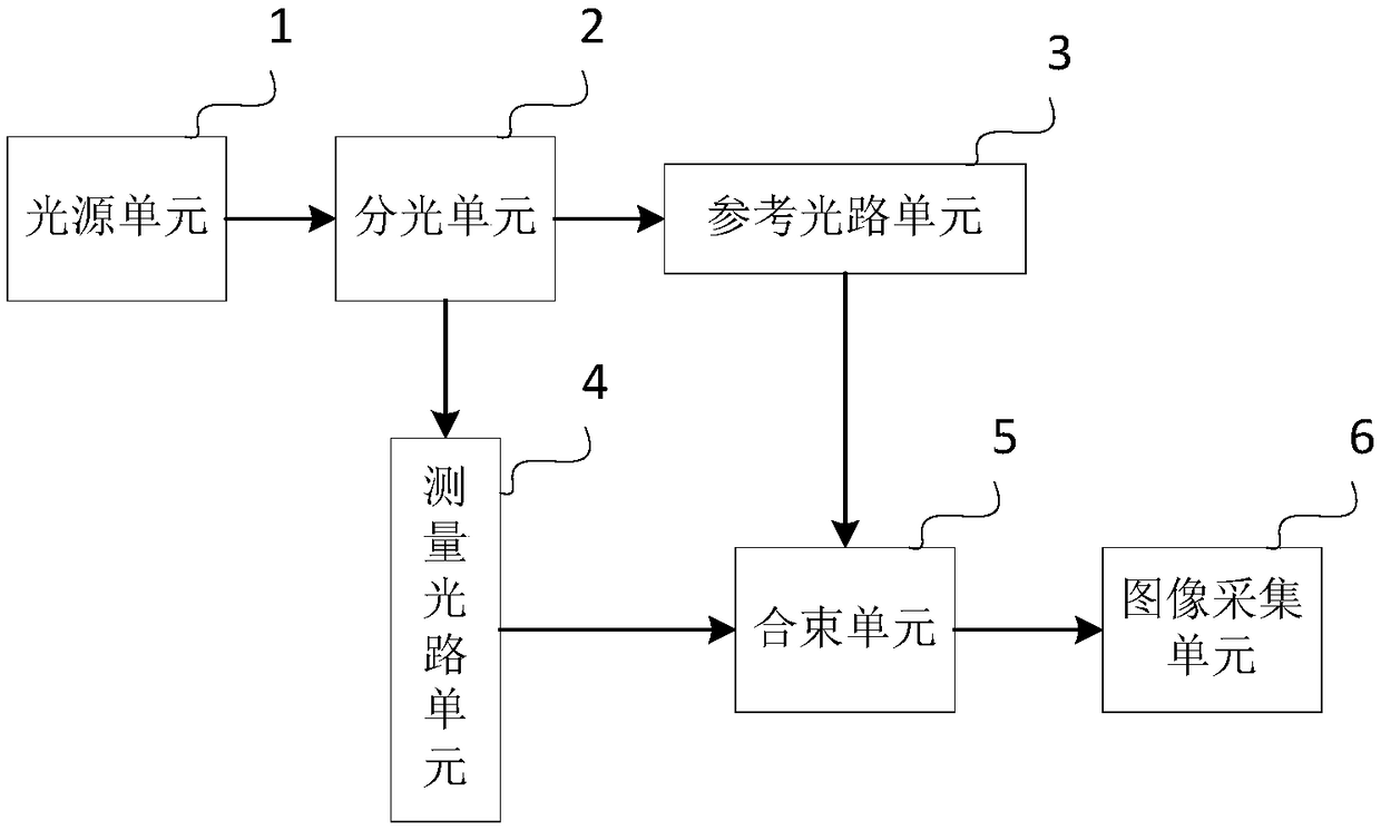
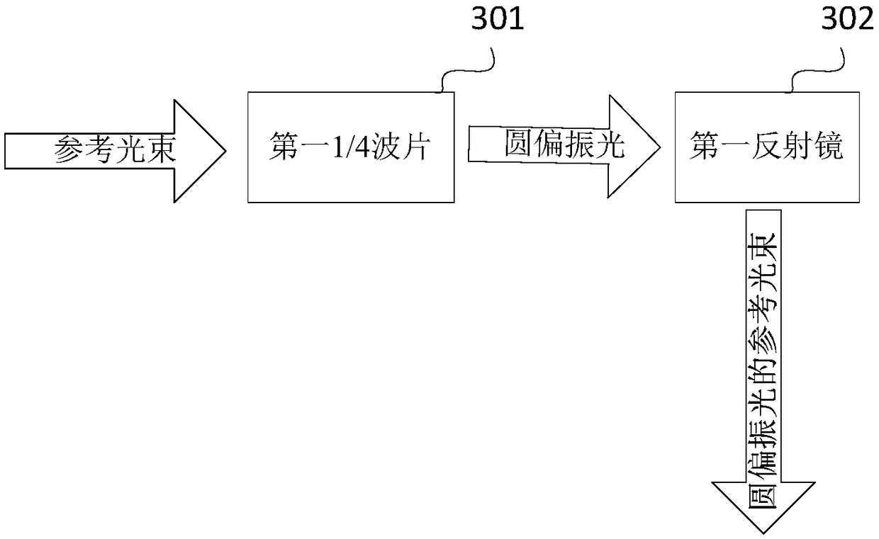
The invention discloses a double-channel simultaneous phase shifting interference microscopic system, and relates to the field of optical interference. The system comprises a light splitting unit, a reference light path unit, a measuring light path unit, a beam combining unit and an image acquisition unit; the light splitting unit is used for separating incident light waves into a measuring lightbeam and a reference light beam, the transmission direction of the measuring light beam and the transmission direction of the reference light beam are perpendicular to each other, and the polarizationplane of the measuring light beam and the polarization plane of the reference light beam are mutually orthogonal; the reference light path unit is used for transmitting the reference light beam and carrying out space domain phase shifting on the reference light beam; the measuring light path unit is used for transmitting the measuring light beam, carrying out space domain phase shifting on the measuring light beam and generating an object light beam after the measuring light beam passes through a to-be-measured object; the beam combining unit is used for combining the reference light beam andthe object light beam after space domain phase shifting; the image acquisition unit is used for splitting the beam obtained after beam combining and acquiring two phase-shifted interference fringe patterns on two channels. The cost and technical difficulty are reduced, the time domain phase shifting function is also achieved on the basis of the space domain simultaneous phase shifting function, and a measuring system can be corrected.

Description

technical field [0001] The invention relates to an optical interference microscope system, in particular to a dual-channel simultaneous phase shift interference microscope system. Background technique [0002] In recent decades, with the development of photoelectric image sensing technology, computer technology, and image processing technology, optical phase measurement microscopy has also made great progress; optical phase measurement microscopy has full-field, fast, high-precision , non-contact, non-damaging advantages, through the photoelectric image sensor (such as CCD, CMOS) to collect an interferogram or multiple interferograms with monotonous changes in phase shift, and use the phase demodulation algorithm to calculate the phase distribution of the sample, At the same time, it realizes the high-precision measurement of the three-dimensional shape information of the sample, and the measurement accuracy can reach 1 / 100 wavelength; it has a wide range of applications in ...

Claims


Application Information

Patent Timeline
IPC IPC(8): G01B11/25G01B9/02
CPCG01B9/02001G01B11/2441G01B11/254
Inventor 吕晓旭孙振达钟丽云王翰林
Owner SOUTH CHINA NORMAL UNIVERSITY
Why Eureka
Try Eureka