Airplane part ultra-high precision end face surface flatness detecting imaging device and detecting method

A flatness detection and imaging device technology, applied in measurement devices, optical devices, instruments, etc., can solve the problems of low detection efficiency and measurement accuracy, difficulty in obtaining accurate measurement results, and lack of detection efficiency imaging devices, etc. High efficiency and measurement accuracy, improved light source gathering, and improved detection efficiency and accuracy

Inactive Publication Date: 2019-03-15
CHANGCHUN AVIATION HYDRAULIC CONTROL
View PDF8 Cites 6 Cited by
  • Summary
  • Abstract
  • Description
  • Claims
  • Application Information

AI Technical Summary

Problems solved by technology

The principle of the least squares method is usually only applied to extremely special cases such as complex shell surfaces and other parts outside the measured plane, and is not used as a routine measurement method
For interferometry, in daily work, due to the need to observe the number of interference fringes generated by the reasonable contact between the part and the flat crystal with the naked eye, when the part presents multiple interference fringes, it is difficult to obtain accurate measurement results, and the detection efficiency and measurement accuracy are very low. , there is currently no corresponding imaging device that can accurately measure flatness and high detection efficiency

Method used


Image

  • Airplane part ultra-high precision end face surface flatness detecting imaging device and detecting method
  • Airplane part ultra-high precision end face surface flatness detecting imaging device and detecting method
  • Airplane part ultra-high precision end face surface flatness detecting imaging device and detecting method

Examples


Embodiment Construction

[0039] The present invention will be described in further detail below in conjunction with the accompanying drawings and embodiments.

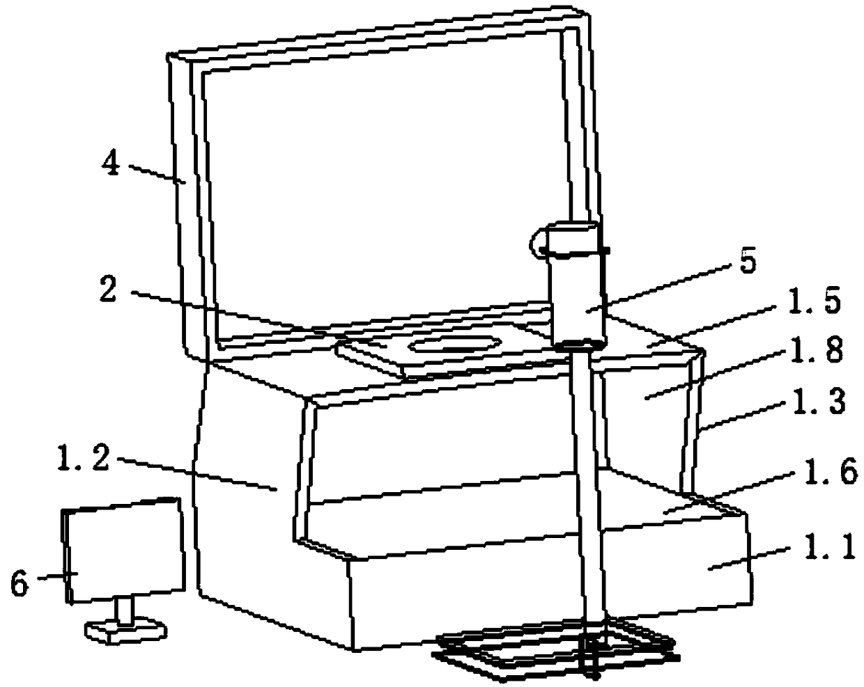
[0040] An ultra-high-precision end face flatness detection imaging device for aviation parts, comprising a solid wood main body box, a flat crystal tray 2, a flat crystal 3, a flat crystal protective cover 4, an interference light source, a CCD sensor, a universal adjustment bracket 5 and a computer 6. The schematic diagram of the three-dimensional structure is as figure 1 shown.

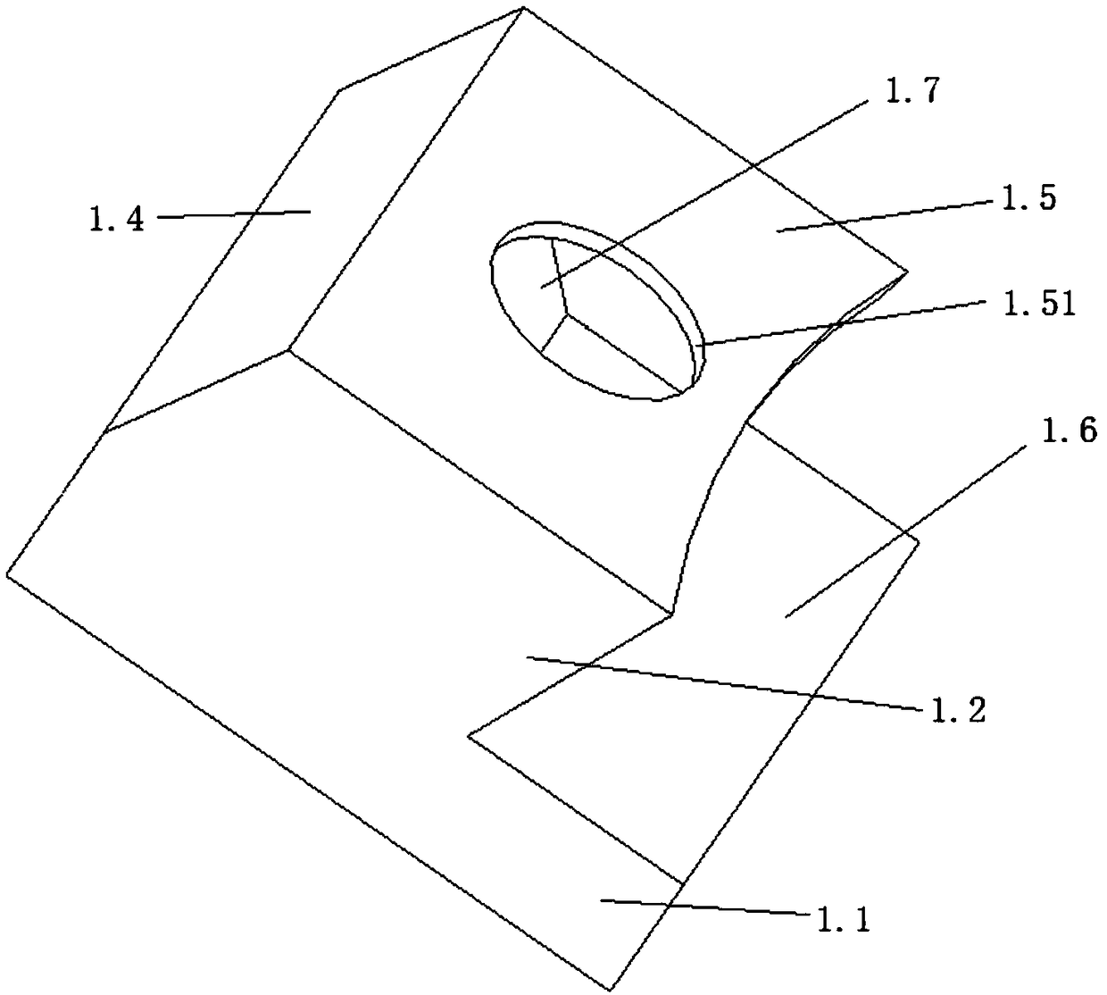
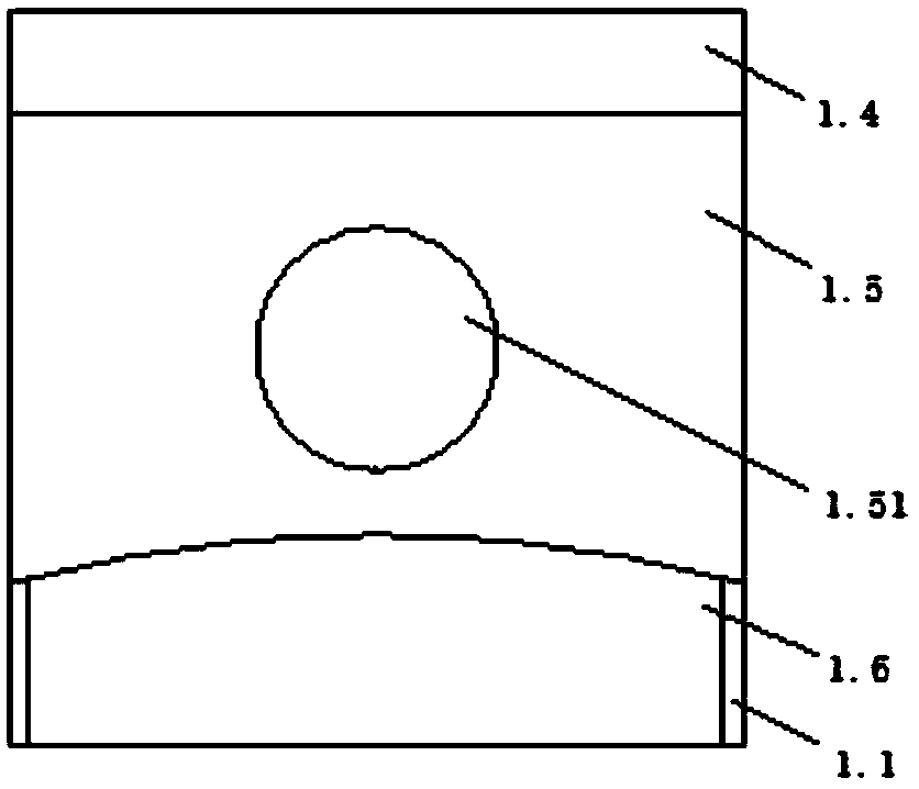
[0041] The structure of the solid wood main box is as follows figure 2 with image 3 , the solid wood main box includes base 1.1, left side panel 1.2, right side panel 1.3, rear side panel 1.4 and upper panel 1.5, base 1.1, left side panel 1.2, right side panel 1.3, rear side panel 1.4 and upper panel 1.5 A cavity, the front of which communicates with the outside world. The left side plate 1.2, the right side plate 1.3 and the rear side plate 1.4 are all instal...


PUM


Abstract

The invention discloses an airplane part ultra-high precision end face surface flatness detecting imaging device and a detecting method, relates to the technical field of surface flatness detecting, and the problems of lower detecting efficiency and measuring accuracy are solved. The device comprises a solid wood body box, an optical flat tray, an optical flat, an interference light source, a CCDsensor, a universal adjusting supporting frame and a computer. A base of the solid wood body box is provided with a plane mirror, a rear side plate is provided with a plane mirror, a left side plate,black shielding layers are arranged on the inner surfaces of a left side plate, a right side plate and an upper plate, and a groove hole for installing the optical flat tray is formed in the upper plate; the optical flat is placed on the optical flat tray, the interference light source is installed in the solid wood body box, and the CCD sensor is connected with the universal adjusting supportingframe and photographs and transmit interference strip images to the computer. According to the device, interference strips are clearly presented on the computer, the defect that the result cannot be efficiently and accurately read when the surface flatness is detected by the optical flat is overcome, and the detection efficiency and accuracy on spare parts are improved.

Description

technical field [0001] The invention relates to the field of flatness detection of mechanical seal end faces, in particular to an imaging device and a detection method for ultra-high-precision end face flatness detection of aviation parts. Background technique [0002] Mechanical seals are widely used in aero-engine valve parts. Mechanical seals are composed of at least one pair of end faces perpendicular to the axis of rotation under the action of fluid pressure and the elastic force (or magnetic force) of the compensation mechanism and the cooperation of auxiliary seals. Combined and relatively sliding to form a device for preventing fluid leakage. [0003] The flatness verification of the end face of ultra-high-precision mechanical seals has always been one of the bottlenecks that plague the accuracy and efficiency of parts inspection in enterprises. The shape tolerance requirements for ultra-high-precision flatness of aviation parts are usually 0.3um, and occasionally 0....

Claims


Application Information

Patent Timeline
Patent Type & Authority Applications(China)
IPC IPC(8): G01B11/30
CPCG01B11/30
Inventor 朱运邰炳芳
Owner CHANGCHUN AVIATION HYDRAULIC CONTROL
Why Eureka
Try Eureka