Circulating fluidized bed waste incineration boiler based on grate and working method thereof

A circulating fluidized bed and waste incineration technology, applied in the combustion method, incinerator, combustion type, etc., can solve the problems of high ash proportion, high CO emission, unstable combustion, etc., to improve stability, uniform combustion, Beneficial for full combustion

Pending Publication Date: 2020-10-13
HUANENG CLEAN ENERGY RES INST
View PDF0 Cites 1 Cited by
  • Summary
  • Abstract
  • Description
  • Claims
  • Application Information

AI Technical Summary

Problems solved by technology

However, there are still some problems in the fluidized bed waste furnace itself, such as high ash ratio, unstable combustion and high CO emissions, which still need further research.

Method used


Image

  • Circulating fluidized bed waste incineration boiler based on grate and working method thereof
  • Circulating fluidized bed waste incineration boiler based on grate and working method thereof
  • Circulating fluidized bed waste incineration boiler based on grate and working method thereof

Examples


Embodiment 1

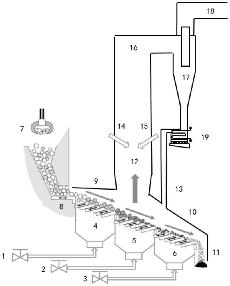
[0035] A kind of circulating fluidized bed garbage incineration boiler based on fire grate of the present invention, as figure 1 , in this embodiment, the feeding system adopts the combination of feeding grab 7 and horizontal reciprocating feeding device 8, and the feeding grab 7 is arranged above the horizontal reciprocating feeding device 8, and the horizontal reciprocating feeding device 8 It is connected with the head end of the grate drying section 4, the tail end of the fire grate drying section 4 is connected with the head end of the fluidized combustion section 5, and the tail end of the fluidized combustion section 5 is connected with the head end of the fire grate burnout section 6, The tail end of the grate burnout section 6 is connected to the slagging pipe 11, and the fluidized combustion section 5 adopts the same grate form as the grate drying section 4 and the grate burnout section 6.

[0036] The lower parts of the grate drying section 4, the fluidized combusti...

Embodiment 2

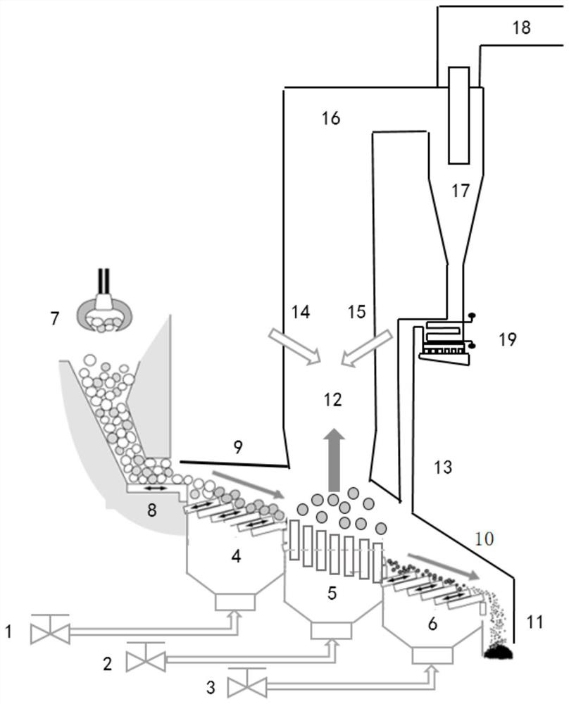
[0040] Such as image 3 , in this embodiment, the feeding system adopts the combination of feeding grab 7 and horizontal reciprocating feeding device 8, and the feeding grab 7 is arranged above the horizontal reciprocating feeding device 8, and the horizontal reciprocating feeding device 8 It is connected with the head end of the grate drying section 4, the tail end of the fire grate drying section 4 is connected with the head end of the fluidized combustion section 5, and the tail end of the fluidized combustion section 5 is connected with the head end of the fire grate burnout section 6, The tail end of the grate burnout section 6 is connected to the slag discharge pipe 11. The fluidized combustion section 5 adopts a fixed hood type, and several fixed hoods are arranged on the air distribution plate to better control the local small hole flow rate and realize the material flow at the same time. fluidized combustion.

[0041] The lower parts of the grate drying section 4, th...


PUM


Abstract

The invention discloses a circulating fluidized bed waste incineration boiler based on a grate and a working method thereof and belongs to the technical field of household waste incineration flue gastreatment. A feeding system is connected with a grate drying section; the grate drying section, a fluidized combustion section and a grate burnout section are sequentially connected, and the lower parts of the grate drying section, the fluidized combustion section and the grate burnout section are respectively connected with a primary air system through air volume adjusting devices; the grate burnout section is connected with a slag discharge pipe; a front arch of the grate is positioned above the grate drying section, and a rear arch of the grate is positioned above the grate burnout section;a hearth is connected with a secondary air system; the upper part of the hearth is connected with a horizontal flue; the horizontal flue is connected with an inlet of a material returning system; a material returning outlet of the material returning system is connected with a material returning port of the boiler through a material returning pipe; and a smoke outlet of the material returning system is connected to a tail flue. The stability of feeding and slag discharging is improved, so that the combustion is uniform and stable, the emission of harmful pollutants is reduced, the combustion efficiency of the boiler is improved, and the risk of blowing out is avoided.

Description

technical field [0001] The invention belongs to the technical field of domestic waste incineration flue gas treatment, and in particular relates to a grate-based circulating fluidized bed waste incineration boiler and a working method thereof. Background technique [0002] A large amount of garbage and solid waste have brought great harm to the environment, mainly manifested as land occupation, air pollution, soil and water pollution. Compared with landfill and composting, the incineration method has the characteristics of volume reduction, weight reduction, on-site processing, fast processing speed, heat energy recovery, and high degree of harmlessness. Therefore, various countries have regarded waste incineration power generation as an important way to develop new energy and waste disposal. [0003] With the urgent need for waste harmless disposal technology and the general trend of national environmental protection and energy conservation, the waste incineration industry...

Claims


Application Information

Patent Timeline
Patent Type & Authority Applications(China)
IPC IPC(8): F23G5/30F23G5/04F23G5/44
CPCF23G5/04F23G5/30F23G5/44F23G5/444F23G2201/10F23G2203/501F23G2207/30
Inventor 蒋敏华高洪培袁野时正海王海涛孙献斌肖平
Owner HUANENG CLEAN ENERGY RES INST
Why Eureka
Try Eureka