3D space scanning uniform light projection display device

A technology of three-dimensional space and display devices, applied in projection devices, optics, optical components, etc., can solve problems such as increasing system complexity and overall machine cost, affecting lighting and projection display effects, and poor light uniformity of integrating square rods, etc. , to achieve improved lighting and display effects, low cost, safe and convenient use

Pending Publication Date: 2019-03-15
合肥全色光显科技有限公司
View PDF0 Cites 5 Cited by
  • Summary
  • Abstract
  • Description
  • Claims
  • Application Information

AI Technical Summary

Problems solved by technology

[0003] In order to improve lighting and display brightness, multiple red, green, and blue semiconductor laser arrays are currently used as display or coherent lighting sources. However, due to the asymmetry of the arrangement, the incident multiple laser beams may deviate from the optical axis, resulting in synthetic color light. Sidebands of other colors will appear when the light is used, resulting in poor light uniformity of the integral square rod, which will affect the lighting and projection display effect
[0004] Due to the high coherence of laser, the laser projected on the screen interferes with each other to produce bright and dark speckles, which is a common speckle phenomenon in laser display. Speckle will lead to blurred projection images and seriously affect the imaging quality; therefore Eliminating speckle effect is a difficult point that laser display technology must overcome
[0005] Existing laser speckle dissipation technologies include: using the diversity of laser wavelengths, vibrating screens, vibrating optical fibers, and using moving scattering sheets, but these methods have limited effects in reducing speckle contrast, and will increase the complexity of the system and the cost of the whole machine

Method used


Image

  • 3D space scanning uniform light projection display device
  • 3D space scanning uniform light projection display device
  • 3D space scanning uniform light projection display device

Examples


Embodiment

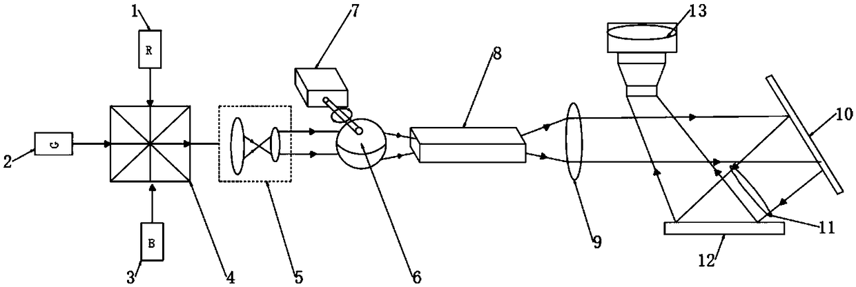
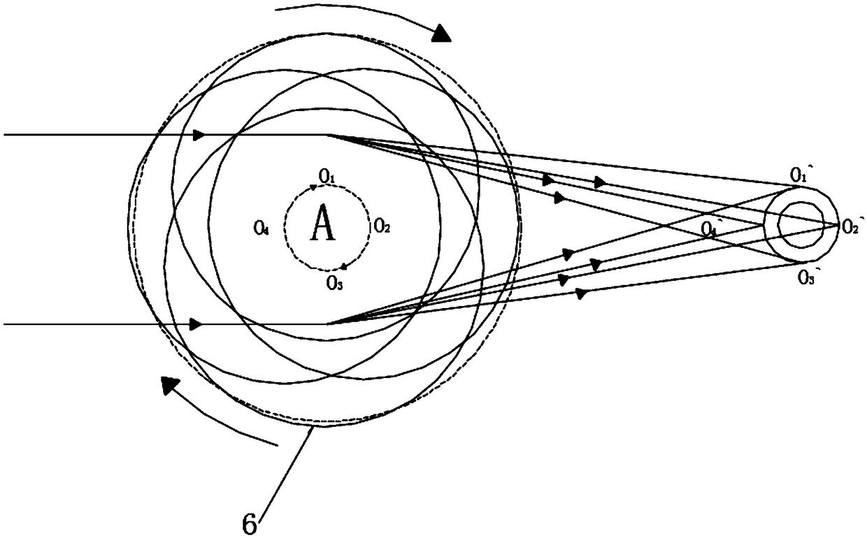
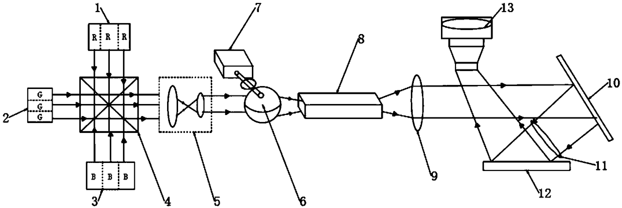
[0028] Example: as Figure 1-5 As shown, the present invention provides a technical solution, a three-dimensional space scanning uniform light projection display device, comprising: a red light semiconductor laser light source module 1, a green light semiconductor laser light source module 2, a blue light semiconductor laser light source module 3, X beam combining prism 4, beam reducing and collimating module 5, eccentric rotating ball lens 6, motor 7, integrating square rod 8, relay lens group 9, mirror 10, collimating lens 11, digital micromirror device (DMD) 12 and projection lens 13, one side of the X beam combining prism is provided with a red light semiconductor laser light source module, a green light semiconductor laser light source module and a blue light semiconductor laser light source module, and the other side of the X beam combining prism is provided with a A beam-shrinking and collimating module, one side of the beam-shrinking and collimating module is provided ...


PUM


Abstract

Provided is a 3D space scanning uniform light projection display device, which comprises a red light semiconductor laser light source module, a green light semiconductor laser light source module, a blue light semiconductor laser light source module, an X beam combining prism, a beam-shrinking collimating module, an eccentric rotating ball lens, an integral square bar, a relay lens group, a reflector, a collimating lens, a DMD and a projection lens. Red, green and blue laser light is combined by the X beam combining prism and then is input in a collimating way to the eccentric rotating ball lens after beam shrinking, so that the position of the focal point is constantly changing, a rotationally scanned image of a ring is approximately formed at the focal plane, uniform rectangular spots are obtained by entering an integrating square bar and are incident on the DMD through the relay lens group, the reflector and a collimating lens for modulation, then a projection display image is obtained, and finally the projection display image is input to the projection lens. The eccentric rotary ball lens technology improves the uniform light effect and also reduces the speckle contrast, and issuitable for the technical field of laser projection display.

Description

technical field [0001] The invention relates to the field of laser projection display, in particular to a three-dimensional space scanning uniform light projection display device. Background technique [0002] Laser display technology is the fourth generation of display technology after black and white display, color display and digital display. Laser projection display technology and traditional display technology have the following significant advantages: (1) The color gamut is wide, and its color gamut coverage is the same as that of traditional NTSC TVs. The color gamut is more than twice, which can represent the colors of nature more realistically; (2) The lifespan of the laser light source used can reach more than 10,000 hours, and the decay process is slow, which can maintain high image quality for a long time and reduce costs; ( 3) High brightness, traditional projector (xenon lamp or mercury lamp), the maximum luminous flux of a single machine can reach 33,000 lumen...

Claims


Application Information

Patent Timeline
Patent Type & Authority Applications(China)
IPC IPC(8): G03B21/20G02B27/10G02B27/09
CPCG03B21/2033G02B27/0955G02B27/126G03B21/206G03B21/208
Inventor 顾春董天浩王贯邓林宵姚昞晖许立新姚培军
Owner 合肥全色光显科技有限公司
Why Eureka
Try Eureka