
Method and device for fitting angular contact roller bearing

A contact roller and mounting device technology, applied to the field of supporting the crankshaft in the internal combustion engine of a motor vehicle, and installing such an angular contact roller bearing, can solve the problem of flange loosening, adverse effects of production costs, and bearing failure, etc. question

Active Publication Date: 2019-03-15
SCHAEFFLER TECH AG & CO KG
View PDF13 Cites 3 Cited by
  • Summary
  • Abstract
  • Description
  • Claims
  • Application Information

AI Technical Summary

Problems solved by technology

[0006] In angular contact roller bearings of this type, although only one of the bearing rings is formed in one piece with only one lateral flange, the share of the cutting work during the production of the raceway and during the machining of the flange and thus the bearing The overall cost of manufacture is significantly less than that of the aforementioned cylindrical roller bearings, however in these angular contact roller bearings the flanges on each additional bearing ring are constructed as separate flange pieces which are additionally They are installed on the bearing rings, and the abutment surfaces of them and the bearing rings that match them require precise manufacturing, which has an adverse effect on their production costs
In addition, in these angular contact roller bearings there is the danger that the individual flanges are not fastened sufficiently to withstand high radial or axial load peaks, so that the flanges can loosen during bearing operation and eventually lead to bearing failure

Method used


Image

  • Method and device for fitting angular contact roller bearing
  • Method and device for fitting angular contact roller bearing
  • Method and device for fitting angular contact roller bearing

Examples


Embodiment Construction

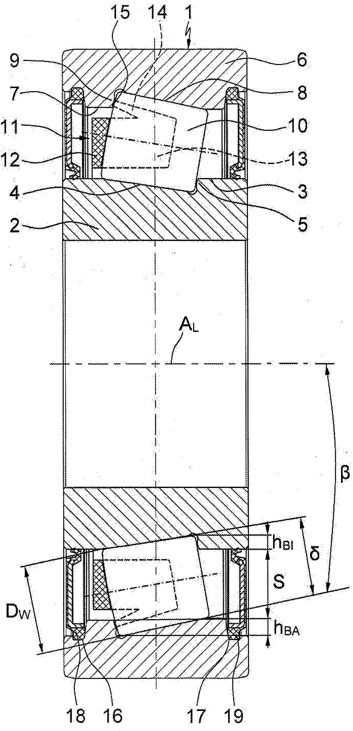
[0040] exist figure 1 shows a cross-section of a single-row angular contact roller bearing 1 which is suitable, for example, to replace the hitherto used deep groove ball bearings for supporting crankshafts in internal combustion engines of motor vehicles. Obviously, this angular contact roller bearing 1 is composed of a bearing inner ring 2 and a bearing outer ring 6. L Arranged inner raceway 4, the minimum diameter of the inner raceway is defined by the flange 5, and the bearing outer ring has a bearing rotation axis A that is also inclined to the radial direction on its inner peripheral surface 7 L The outer raceway 8 is arranged, the maximum diameter of the outer raceway is limited by the flange 9 . Between the bearing rings 2, 6 there are also arranged a plurality of rolling elements 10 rolling on their raceways 4, 8, which are kept at a uniform distance from each other in the circumferential direction by the bearing cage 11 .

[0041] Also in figure 1 It can also be ...


PUM


Abstract

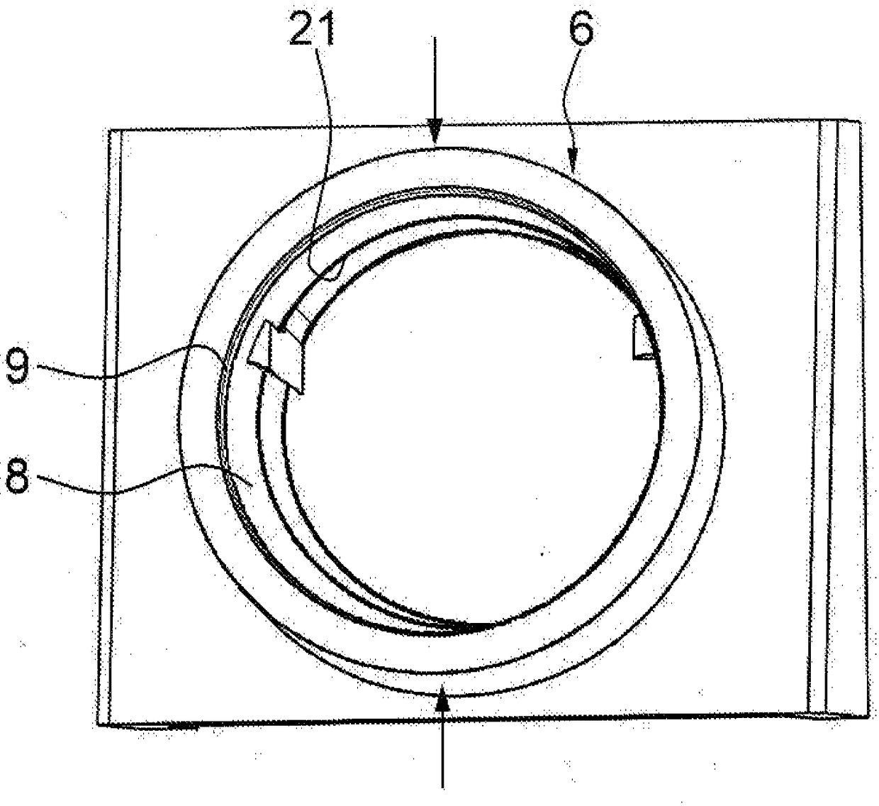
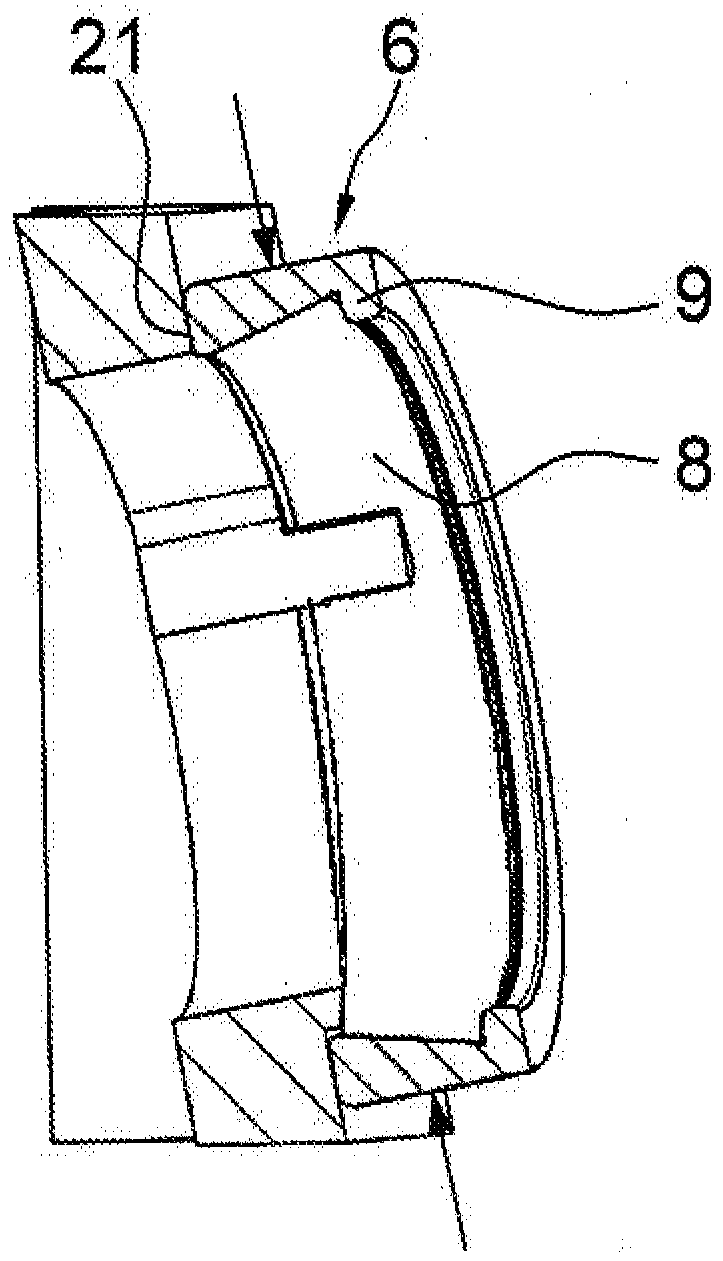
The invention relates to a method for fitting an angular contact roller bearing (1), comprising an inner bearing ring (2) having an inner track (4) arranged on the outer peripheral surface (3) of theinner bearing ring and inclined with respect to the axis of rotation of the bearing (AL), and a rim (5) delimiting said track at the smallest diameter thereof, an outer bearing ring (6) having an outer track (8) arranged on the inner peripheral surface (7) of the outer bearing ring and inclined with respect to the axis of rotation of the bearing, and a rim (9) delimiting said track at the greatestdiameter thereof, and also comprising a plurality of roller bearing elements (10) which are arranged between the bearing rings and roll on the track and are held at uniform distances from one anotherin the circumferential direction by a bearing cage (11). The outer peripheral surface of the inner bearing ring and the inner peripheral surface of the outer bearing ring are in each case cylindricaland extend outside the tracks at least in some sections coaxially with respect to the axis of rotation of the bearing, and the tracks of both bearing rings are in each case integrated conically intothe cylindrical peripheral surfaces, such that the rims which are produced in this way and in each case delimit the tracks on one side are in each case formed in one piece with the bearing rings. According to the invention, the fitting of the angular contact roller bearing takes place according to an eccentric pivot fitting method borrowed from the eccentric fitting method known for deep groove ball bearings. The invention further relates to a device for performing the fitting method.

Description

technical field [0001] The invention relates to a method for mounting, in particular single row, angular contact roller bearings which can be used particularly advantageously for supporting crankshafts in internal combustion engines of motor vehicles. The invention also relates to a device for mounting such an angular contact roller bearing. Background technique [0002] The bearing type most often used to support crankshafts in internal combustion engines of motor vehicles is the single row deep groove ball bearing because it is characterized by an equally high radial and axial load carrying capacity and because of its low friction it also has Highest speed limit of all bearing types. These deep groove ball bearings consist of a bearing outer ring and a bearing inner ring in a known manner and of a plurality of bearing balls arranged between these bearing rings, which are machined into the inner side of the bearing outer ring and the outer side of the bearing inner ring T...

Claims


Application Information

Patent Timeline
Patent Type & Authority Applications(China)
IPC IPC(8): F16C43/06F16C19/36F16C33/46F16C33/49F16C43/08F16C33/58
CPCF16C43/06F16C19/364F16C33/4605F16C33/495F16C33/585F16C19/36F16C43/08
Inventor 雷纳·艾德洛特赖因哈德·伦佩尔恩斯特·盖格尔海因里希·霍夫曼
Owner SCHAEFFLER TECH AG & CO KG
Learn More