Ultrasonic probe coupling assembly and ultrasonic probe mechanism

A technology of ultrasonic probe and coupling parts, which is applied in the directions of ultrasonic/sonic/infrasonic diagnosis, ultrasonic/sonic/infrasonic Permian technology, ultrasonic/sonic/infrasonic image/data processing, etc. It can solve the problem of solid-state coupling patches and probes Problems such as poor fit, troublesome use of solid-state coupling patches, and discomfort of gel-like coupling agents, etc., to achieve stable and effective transmission, good fit, and good assembly

Pending Publication Date: 2019-03-19
SHENZHEN LEPUYUAN MEDICAL TECH CO LTD
View PDF0 Cites 5 Cited by
  • Summary
  • Abstract
  • Description
  • Claims
  • Application Information

AI Technical Summary

Problems solved by technology

[0005] Aiming at the deficiencies in the prior art, the present invention provides an ultrasonic probe coupling assembly and an ultrasonic probe assembly to solve the discomfort in the use of a gel-like coupling agent in the prior art, the trouble of using a solid-state coupling patch, and the solid-state coupling patch and probe. The problem of poor fit

Method used


Image

  • Ultrasonic probe coupling assembly and ultrasonic probe mechanism
  • Ultrasonic probe coupling assembly and ultrasonic probe mechanism
  • Ultrasonic probe coupling assembly and ultrasonic probe mechanism

Examples


Embodiment 1

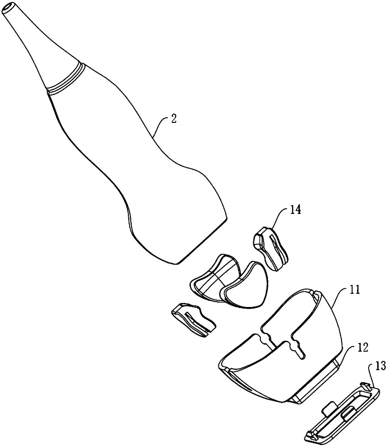
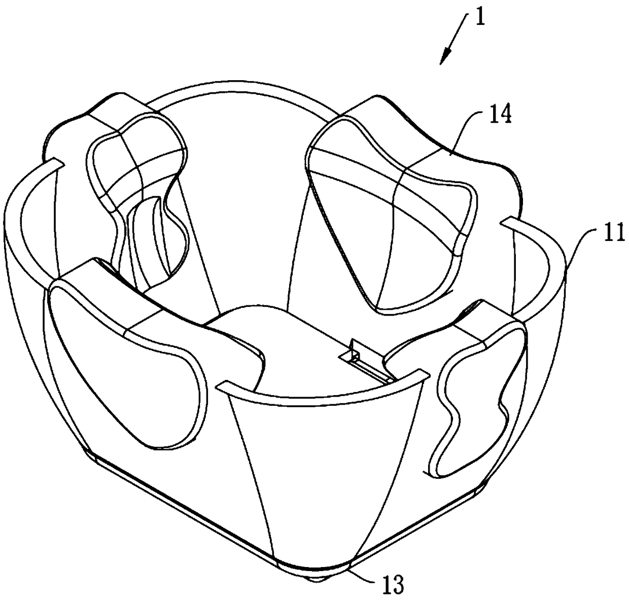
[0044] In this embodiment, the solid coupling part 12 is fixed in the probe ferrule 11 by injection molding. The solid coupling 12 is a solid coupling gel. At the beginning of injection molding, the coupling gel can flow, and the coupling gel forms a joint force with the probe ferrule 11 while solidifying, thereby being fixed in the probe ferrule 11 to form a solid state. Coupling 12.

[0045] Please also refer to Figure 3 to Figure 5 , the solid-state coupling 12 is molded on the probe ferrule 11 by injection molding, which saves the assembly of the solid-state coupling 12 on the probe ferrule 11 and effectively avoids damage to the solid-state coupling 12 when assembling the solid-state coupling 12 Pollution, due to the soft feature of the solid coupling 12, it can also effectively overcome the damage to the solid coupling 12 during assembly, and because the solid coupling 12 is easily deformed during assembly, it is easy to cause the assembly of the solid coupling 12. In...

Embodiment 2

[0071] Please also refer to Figure 8 to Figure 10 The difference between this embodiment and Embodiment 1 is that in this embodiment, the solid coupling 12 includes a plastic part 12a and a solid coupling part 12b, and the plastic part 12a is embedded in the solid coupling part 12b so that the solid coupling 12 forms as one. The plastic part 12 a becomes the annular protrusion of the solid coupling part 12 , and the solid coupling part 12 is fixed in the probe ferrule 11 through the plastic part 12 a. By embedding the plastic part 12a in the solid coupling part 12b, the strength of the connection structure of the solid coupling part 12 is enhanced and the solid coupling part 12 is firmly fixed on the probe ferrule 11 .

[0072] The plastic part 12a is directly molded in the solid coupling part 12b, such as Figure 10 As shown, in order to clearly reflect the structure of the plastic part 12a, the plastic part 12a is separated from the solid coupling part 12b. The solid cou...

Embodiment 3

[0080] The difference between this embodiment and Embodiment 1 is that in this embodiment, the solid coupling part 12 and the probe ferrule 11 are separated, and the solid coupling part 12 is formed by coupling gel injection molding to form interconnected protrusions. The lifting part 122 and the fixing part 121 , the pressing part 13 fixes the solid coupling part 12 on the probe ferrule 11 by pressing the fixing part 121 on the probe ferrule 11 .

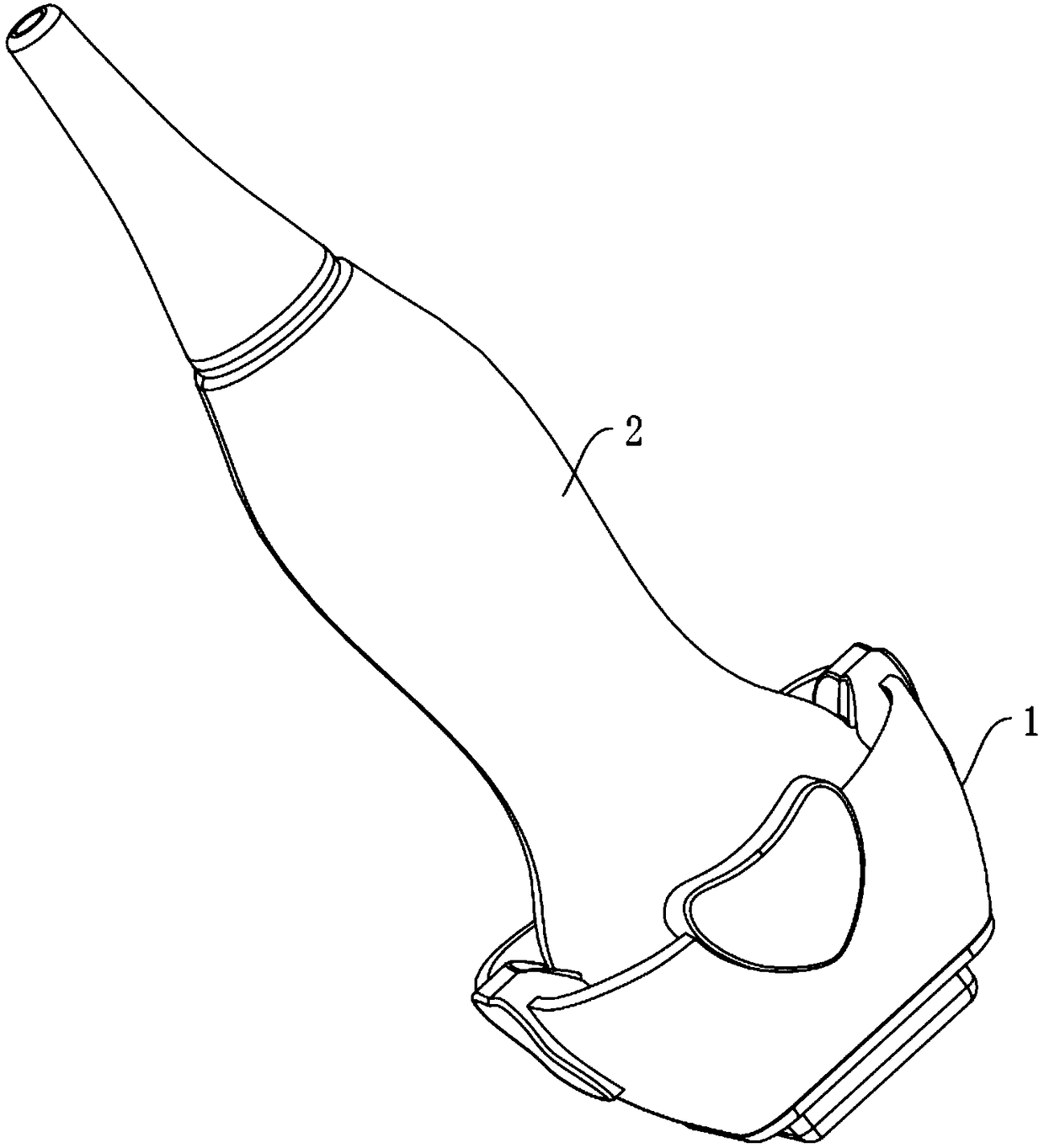
[0081] As mentioned above, the ultrasonic probe coupling assembly 1 and the ultrasonic probe 2 constitute the ultrasonic probe mechanism.


PUM


Abstract

The invention provides an ultrasonic probe coupling assembly and an ultrasonic probe mechanism. The ultrasonic probe coupling assembly includes a probe clamping sleeve and a solid coupling part. The probe clamping sleeve is used for sleeving an ultrasonic probe. The solid coupling part is fixed in the probe clamping sleeve, one side of the solid coupling part is located in the probe clamping sleeve and used for fitting the ultrasonic probe, and the other side of the solid coupling part protrudes from the probe clamping sleeve and is used for being in contact with the skin. The ultrasonic probemechanism includes the ultrasonic probe coupling assembly and the ultrasonic probe. By pushing the ultrasonic probe, the end of the ultrasonic probe fits with the solid coupling part located on the inner side of the probe clamping sleeve, so that the ultrasonic probe is in seamless transition with the skin, the air between the ultrasonic probe and the skin is eliminated, and the stable and effective transmission of ultrasonic waves is ensured. An ultrasonic probe assembly includes the ultrasonic probe coupling assembly, a gel coupling agent does not need to be used, and the adopted solid coupling part can well fit with the ultrasonic probe.

Description

technical field [0001] The invention relates to the field of ultrasonic detection equipment, in particular to an ultrasonic probe coupling assembly and an ultrasonic probe mechanism. Background technique [0002] Ultrasound examination is the guarantee for doctors to obtain information, and it is also the key to diagnosing diseases. At present, during echocardiography and superficial examination, due to the very small field of view of the phased array near-field and artifacts in the near-field, it is very difficult to see the blood flow around the apex of the heart clearly. It is difficult to make an accurate judgment on the blood flow, and the linear array probe cannot see the blood flow under the skin clearly, which brings great troubles to the doctor's diagnosis work. [0003] At present, in the process of ultrasonic examination, it is necessary to apply a gel-like coupling agent on the examination site first, and then slide the ultrasonic probe on it for examination. Af...

Claims


Application Information

Patent Timeline
Patent Type & Authority Applications(China)
IPC IPC(8): A61B8/00A61B8/08
CPCA61B8/4444A61B8/0883
Inventor 王彩丰罗志刚马俊英
Owner SHENZHEN LEPUYUAN MEDICAL TECH CO LTD
Why Eureka
Try Eureka