
Automatic feeding and discharging device of punch machine

A technology for automatic loading and unloading and stamping machine tools, which is applied to the supporting devices of stamping machine tools and the field of automatic loading and unloading devices for stamping machine tools, and can solve the problems of poor part supply fluency, high labor costs, and low work efficiency

Active Publication Date: 2019-03-19
YANGZHOU UNIV
View PDF5 Cites 4 Cited by
  • Summary
  • Abstract
  • Description
  • Claims
  • Application Information

AI Technical Summary

Problems solved by technology

[0005] The purpose of the present invention is to solve the defects that in the current manufacturing process of stamping parts, the feeding and discharging process is basically carried out manually. This method has low work efficiency, poor part supply fluency, high labor cost, and cannot meet the actual needs of current enterprises. , put forward an automatic loading and unloading device for stamping machine tools, so as to realize the automation and intelligence of product production, reduce labor costs, continuously increase the production and manufacturing efficiency of products, and further enhance the core competitiveness of enterprises in the market

Method used


Image

  • Automatic feeding and discharging device of punch machine
  • Automatic feeding and discharging device of punch machine
  • Automatic feeding and discharging device of punch machine

Examples


Embodiment Construction

[0026] The present invention will be further described below in conjunction with accompanying drawing:

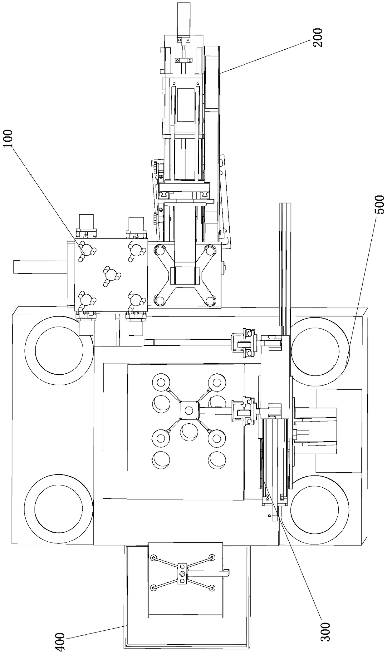
[0027] Such as figure 1 As shown, an automatic loading and unloading device for a stamping machine tool is composed of a hopper 100, a loading mechanism 200, a double-speed manipulator 300, a blanking mechanism 400, and a machine tool body 500.

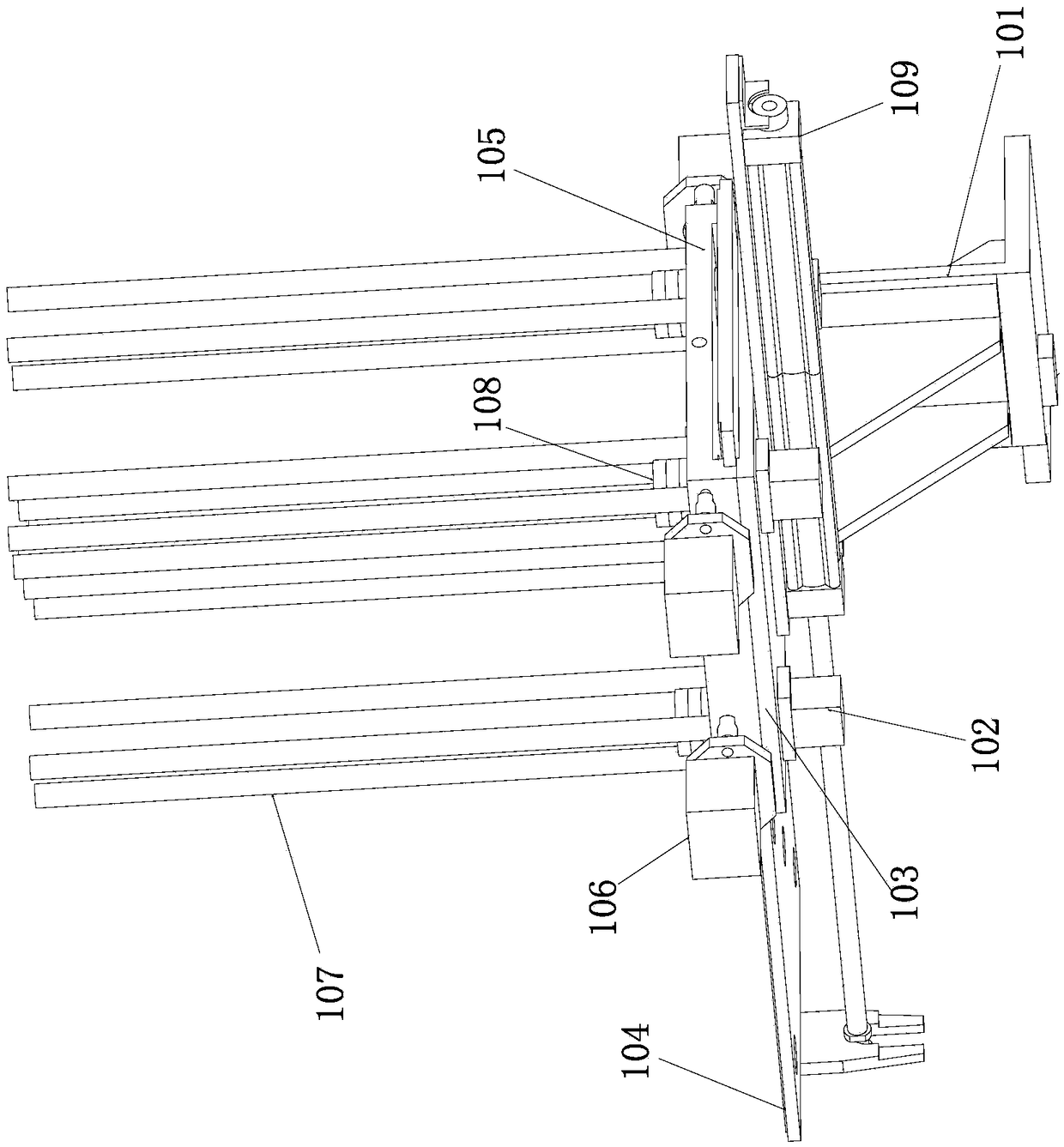
[0028] Such as figure 2 As shown, an automatic loading and unloading device for a stamping machine tool, the silo 100 is composed of a silo bracket 101, a material supporting mechanism 102, a bottom plate 103, a feeding tray 104, a silo base plate 105, a material limiting mechanism 106, a silo column 107, and a workpiece 108 It is formed with the first cylinder 109; the lower end of the bin 100 is fixed on the bin bracket 101, the bin bracket 101 is fixedly arranged on the machine tool body 500, and the supporting mechanism 102 is arranged around the base plate 103, and the supporting mechanism 102 is arranged on the base plate 1...


PUM


Abstract

The invention provides an automatic feeding and discharging device of a punch machine, and belongs to the technical field of material molding engineering equipment. The automatic feeding and discharging device is structurally composed of a stock bin, a feeding mechanism, a double speed manipulator and a discharging mechanism, and workpieces are conveyed for the feeding mechanism by a feed tray through a first cylinder; a sucker mechanism on the feeding mechanism is vertically moved through a second cylinder, and used for conveying the workpieces to the double speed manipulator through a motoron the feeding mechanism and a ball screw horizontally; the workpieces are cleaned through a brush, and a discharging bowl group is used for storing the workpieces conveyed by the sucker mechanism; finished products are stored and waste materials are filtered upon completion of machining by the machine body; and the discharging bowl group is used for conveying the materials to the discharging mechanism through a belt transmission device horizontally, and the workpieces conveyed by the double speed manipulator are sucked through the sucker mechanism on a material pushing mechanism. The automatic feeding and discharging device is novel in structure, and the working principles are clear; the shortcomings of low working efficiency of traditional feeding and discharging procedures, poor fluencyof part supply, high labor cost and the like are overcome; and the production automation and intellectualization of products are achieved, and the labor cost is reduced.

Description

technical field [0001] The invention belongs to the technical field of material forming engineering equipment, and relates to a matching device of a stamping machine tool, in particular to an automatic loading and unloading device of a stamping machine tool. Background technique [0002] Stamping processing is a production technology that uses the power of conventional or special stamping equipment to directly deform the sheet metal in the mold to obtain product parts of a certain shape, size and performance. Sheet metal, mold and equipment are the three elements of stamping processing. According to the stamping processing temperature, it is divided into hot stamping and cold stamping. The former is suitable for sheet metal processing with high deformation resistance and poor plasticity; the latter is carried out at room temperature and is a commonly used stamping method for thin plates. It is one of the main methods of metal plastic processing (or pressure processing). ...

Claims


Application Information

Patent Timeline
IPC IPC(8): B21D43/11B21D43/18B21D45/02B08B1/02
CPCB21D43/026B21D43/11B21D43/18B21D45/02B08B1/20B08B1/12
Inventor 张善文刘旭魏鑫苗杰缪宏张燕军刘思幸张剑峰
Owner YANGZHOU UNIV
Learn More