
Diesel engine particulate filter regeneration system and methods

A particulate filter, engine system technology, applied in the direction of engine components, combustion engine, engine control, etc., to achieve the effect of improving particulate filter regeneration, generating consistency, and reducing possibility

Pending Publication Date: 2019-03-19
FORD GLOBAL TECH LLC
View PDF0 Cites 0 Cited by
  • Summary
  • Abstract
  • Description
  • Claims
  • Application Information

AI Technical Summary

Problems solved by technology

As a result, post-injected fuel may participate in combustion within the cylinder during subsequent cylinder cycles, which may be undesirable

Method used


Image

  • Diesel engine particulate filter regeneration system and methods
  • Diesel engine particulate filter regeneration system and methods
  • Diesel engine particulate filter regeneration system and methods

Examples


Embodiment Construction

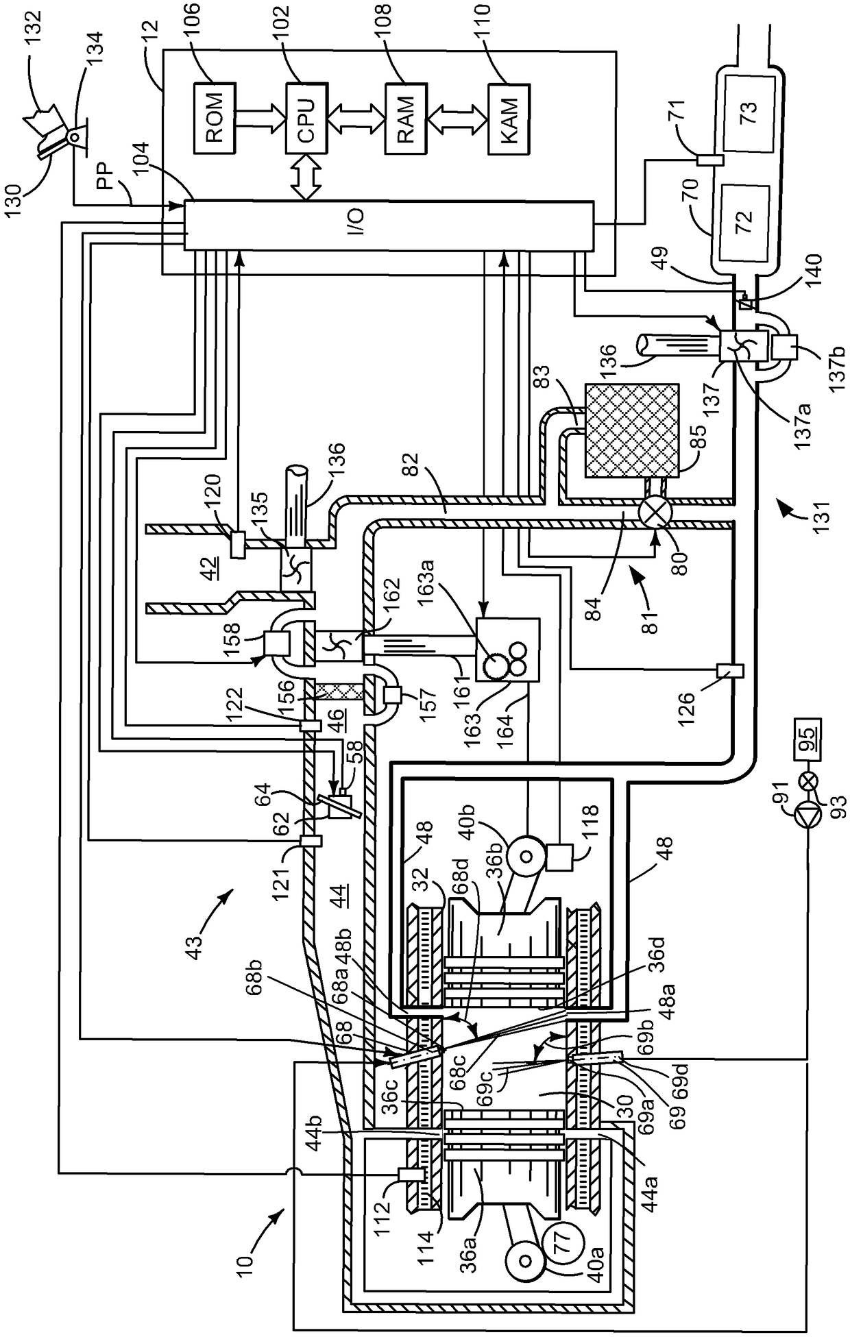
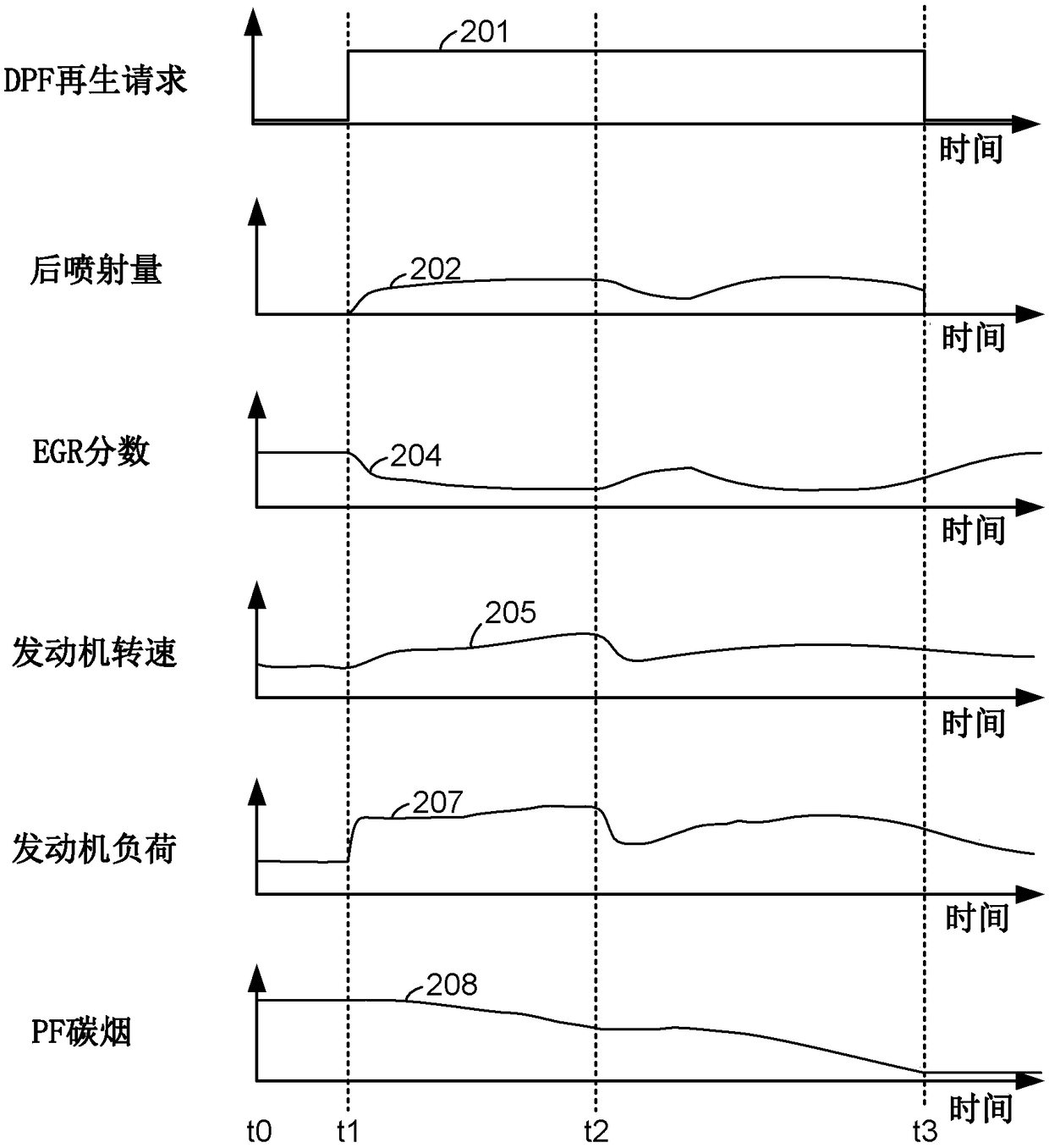
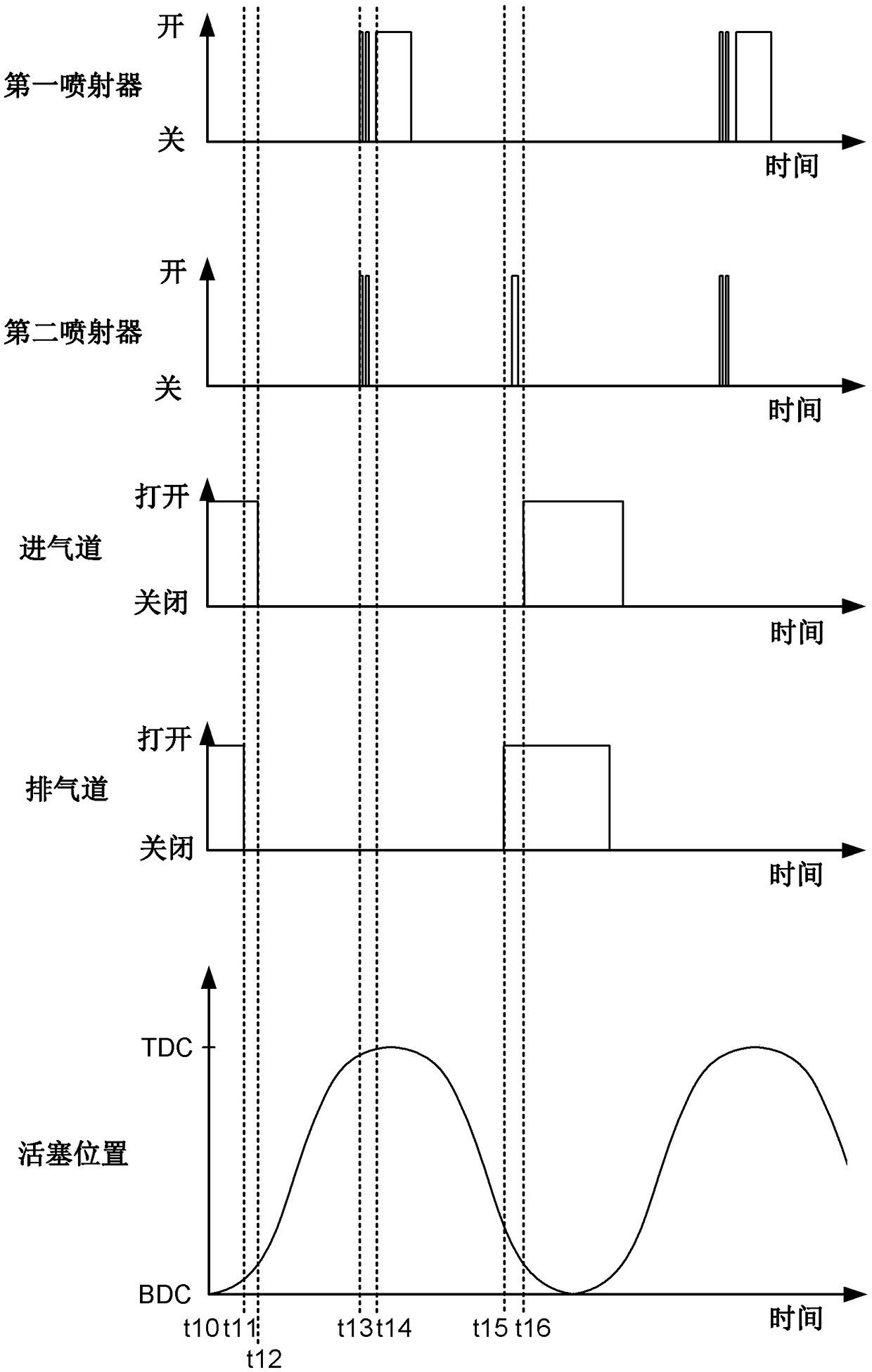
[0012] This specification relates to regenerating particulate filters for two-stroke diesel engines. figure 1 An example of a supercharged two-stroke diesel engine is shown. figure 1 The diesel engine in is an opposed piston engine, but the methods described herein can also be applied to two-stroke engines comprising a single piston in each engine cylinder. figure 2 An example particulate filter regeneration sequence is shown. image 3 The fuel injection timing for a two-stroke diesel engine is shown in . Figure 4 A method for regenerating a particulate filter is shown in .

[0013] refer to figure 1 , an opposed-piston internal combustion engine 10 comprising a plurality of cylinders, one of which is at figure 1 shown in . The controller 12 receives from figure 1 signals of various sensors, and employs figure 1 various actuators to adjust engine operation based on the received signals and instructions stored on the controller's memory.

[0014] Engine 10 includes cy...


PUM


Abstract

The invention relates to a diesel engine particulate filter regeneration system and methods, and describes methods and systems for supplying post injection fuel to a two stroke diesel engine. In one example, post injection fuel timing is adjusted responsive to an amount of internal residual combustion products in a cylinder so that less post injected fuel may be trapped in the cylinder for a subsequent cycle of the cylinder. The start of post injection fuel timing and the amount of post injection fuel may be adjusted responsive to internal residual in the cylinder.

Description

Background technique [0001] Diesel engines can include particulate filters in their exhaust systems to trap carbonaceous soot that can be produced as a byproduct of combustion. Over a period of time, the particulate filter may be filled with soot such that it may provide a more significant restriction on the exhaust. The particulate filter may be regenerated by increasing the exhaust temperature and supplying an oxygen-enriched exhaust mixture to the particulate filter such that soot remaining within the particulate filter is combusted, thereby regenerating the particulate filter. [0002] One method of increasing exhaust temperature is to supply fuel to the oxidation catalyst that does not participate in combustion within the engine cylinders. The fuel is burned in the oxidation catalyst to increase the temperature of the exhaust gas, which then increases the temperature of the particulate filter so that the soot in the particulate filter can be combusted, thereby regenerati...

Claims


Application Information

Patent Timeline
Patent Type & Authority Applications(China)
IPC IPC(8): F02D41/40F02D41/30F02D41/02
CPCF02D41/029F02D41/3094F02D41/405F01B7/14F02B23/02F02B37/04F02B39/04F02B75/28F02D41/0062F02D2041/389F02D2400/04F02M26/01Y02T10/12Y02T10/40
Inventor E·M·库尔茨E·J·卡斯塔尼斯
Owner FORD GLOBAL TECH LLC
Learn More