A kind of moving scroll and scroll compressor

A scroll compressor and moving scroll technology, applied in the field of compressors, can solve problems such as collision and friction, and achieve the effects of reducing friction, compact structure and improving efficiency

Active Publication Date: 2021-07-20
ZHUHAI GREE REFRIGERATION TECH CENT OF ENERGY SAVING & ENVIRONMENTAL PROTECTION
View PDF0 Cites 0 Cited by
  • Summary
  • Abstract
  • Description
  • Claims
  • Application Information

AI Technical Summary

Problems solved by technology

[0005] In order to solve the problem of the axial sliding of the radial bearing and the collision and friction with other components during the axial movement of the eccentric sleeve in the prior art, the present invention provides a movable scroll and a scroll compressor

Method used


Image

  • A kind of moving scroll and scroll compressor
  • A kind of moving scroll and scroll compressor
  • A kind of moving scroll and scroll compressor

Examples


Embodiment 1

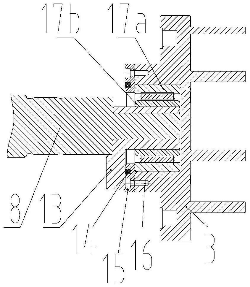
[0042] Such as Figures 1 to 3 As shown, the present invention provides a movable scroll 3,

[0043] The back of the movable scroll 3 is provided with an annular bearing protrusion coaxial therewith, and the inner cavity of the bearing protrusion constitutes a bearing hole;

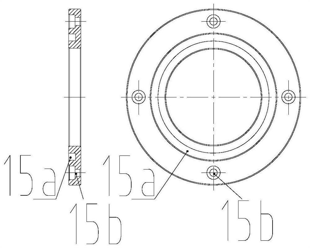
[0044] The outer end surface of the bearing protrusion is provided with a limiting member 15; the outer end surface of the limiting member 15 is provided with a wear-resistant member.

[0045] The limit piece 15 arranged on the outer end surface of the bearing protrusion can axially limit the radial bearing 17 when the bearing protrusion is thermally deformed or subjected to uneven force, and the complicated processing and material extrusion process are omitted The wear-resistant parts arranged on the outer end surface of the limiter 15 can effectively avoid the direct collision with the bearing protrusion when the eccentric sleeve 13 moves up, greatly reducing the friction between the eccentric sleeve 1...

Embodiment 2

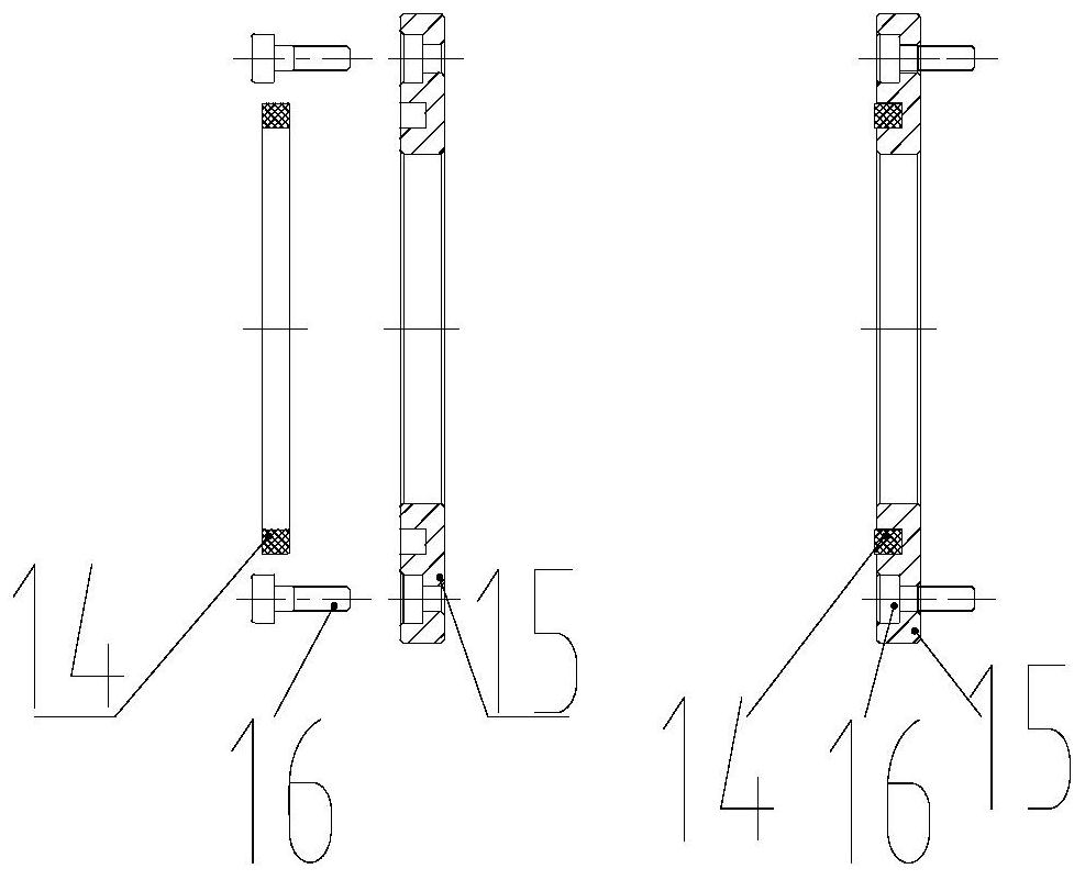
[0052] Such as Figure 4 and Figure 5 As shown, the difference between this embodiment and Embodiment 1 is that the limiting member 15 is fixedly connected to the bearing hole through interference fit; specifically:

[0053] One end of the limiter 15 is provided with an annular first protrusion whose outer diameter is equal to the outer diameter of the limiter 15 and whose inner diameter is smaller than the inner diameter of the limiter 15. The outer end surface of the bearing protrusion is provided with an inner diameter equal to The inner diameter and outer diameter of the bearing hole are smaller than the outer diameter of the bearing hole, and the ring-shaped second protrusion has an interference fit between the inner wall surface of the first protrusion and the outer wall surface of the second protrusion to realize the position limiting Part 15 is fixedly connected with the outer end surface of the bearing protrusion;

[0054] The height of the first protrusion is less...

Embodiment 3

[0056] Such as Figure 6 and Figure 7 As shown, the difference between this embodiment and Embodiment 1 is that the limiting member 15 is fixedly connected to the bearing hole through interference fit; specifically:

[0057] Further, one end of the limiting member 15 is provided with an annular third protrusion whose inner diameter is equal to the inner diameter of the limiting member 15 and whose outer diameter is smaller than the outer diameter of the limiting member 15, and the outer end surface of the bearing protrusion is provided with There is an annular fourth protrusion whose outer diameter is equal to the outer diameter of the bearing hole and whose inner diameter is smaller than the inner diameter of the bearing hole. The outer wall surface of the third protrusion and the inner wall surface of the fourth protrusion are interference fit to realize the The fixed connection between the limiting member 15 and the outer end surface of the bearing protrusion;

[0058] T...


PUM


Abstract

The present invention relates to a movable scroll and a scroll compressor, characterized in that, the back of the movable scroll is provided with an annular bearing protrusion coaxial therewith, and the inner cavity of the bearing protrusion constitutes a bearing hole; The outer end surface of the bearing protrusion is provided with a limit piece; the outer end surface of the limit piece is provided with a wear-resistant piece. The limiter can axially limit the radial bearing when the bearing hole is thermally deformed or under uneven force, and saves complicated processing and material extrusion processes; the wear-resistant part can effectively prevent the eccentric sleeve from moving up The direct collision with the bearing protrusion greatly reduces the friction between the eccentric sleeve and other components, thereby reducing the damage of parts caused by collision and friction, and improving the efficiency of the compressor.

Description

technical field [0001] The invention relates to the technical field of compressors, in particular to a movable scroll and a scroll compressor. Background technique [0002] Scroll compressor is a type of compressor with a wide range of applications and relatively mature technology. It mainly relies on the reciprocating increase and decrease of the volume of the moon-shaped cavity between the orbiting scroll and the fixed scroll to realize the compression of the working fluid. There is a bearing hole on the back of the moving scroll. The bearing hole fixes the outer ring of the radial bearing. The inner ring of the bearing is interference-fitted with the eccentric sleeve for balancing the weight. The inner hole of the eccentric sleeve is inserted into the eccentric part of the crankshaft. When the crankshaft rotates, The eccentric portion drives the movable scroll through the eccentric sleeve. [0003] The outer ring of the radial bearing needs to be fixed in the bearing hol...

Claims


Application Information

Patent Timeline
Patent Type & Authority Patents(China)
IPC IPC(8): F04C18/02F04C23/02F04C29/00F16C9/02
CPCF04C18/0253F04C23/02F16C9/02
Inventor 魏会军李雪峰刘韵康小丽陈肖汕
Owner ZHUHAI GREE REFRIGERATION TECH CENT OF ENERGY SAVING & ENVIRONMENTAL PROTECTION
Why Eureka
Try Eureka