Laser light source of diffractive optical element coherent synthesis based on active optical feedback of ring cavity

A laser light source, coherent synthesis technology, applied in lasers, laser parts, optics, etc., can solve the problems of phase-locking effect being difficult to maintain stability, loss of seeds, laser frequency bandwidth, etc., to improve synthesis efficiency and total output power, solve Brightness enhancement, the effect of ensuring stable operation

Active Publication Date: 2019-03-19
SHANGHAI INST OF OPTICS & FINE MECHANICS CHINESE ACAD OF SCI
View PDF5 Cites 4 Cited by
  • Summary
  • Abstract
  • Description
  • Claims
  • Application Information

AI Technical Summary

Problems solved by technology

However, turning off the auxiliary main oscillation may cause a safety hazard in the fiber amplifier array, that is, the amplifier loses its seed when the feedback loop is accidentally blocked, resulting in severe self-oscillation and damage to the amplifier
Therefore, improving the brightness of the laser output from the passive coherent combining system of the all-optical feedback ring cavity and protecting the system safety of the amplifier have become an irreconcilable contradiction
In addition, the frequency bandwidth and high phase noise of the existing all-optical feedback ring cavity output laser, and the phase-locking effect is difficult to maintain stability, which seriously hinders the prospect of subsequent expansion and application of high-power common-aperture coherent synthesis light sources

Method used


Image

  • Laser light source of diffractive optical element coherent synthesis based on active optical feedback of ring cavity

Examples


Embodiment Construction

[0025] The present invention will be further described in detail below in conjunction with the accompanying drawings, but the protection scope of the present invention should not be limited thereby.

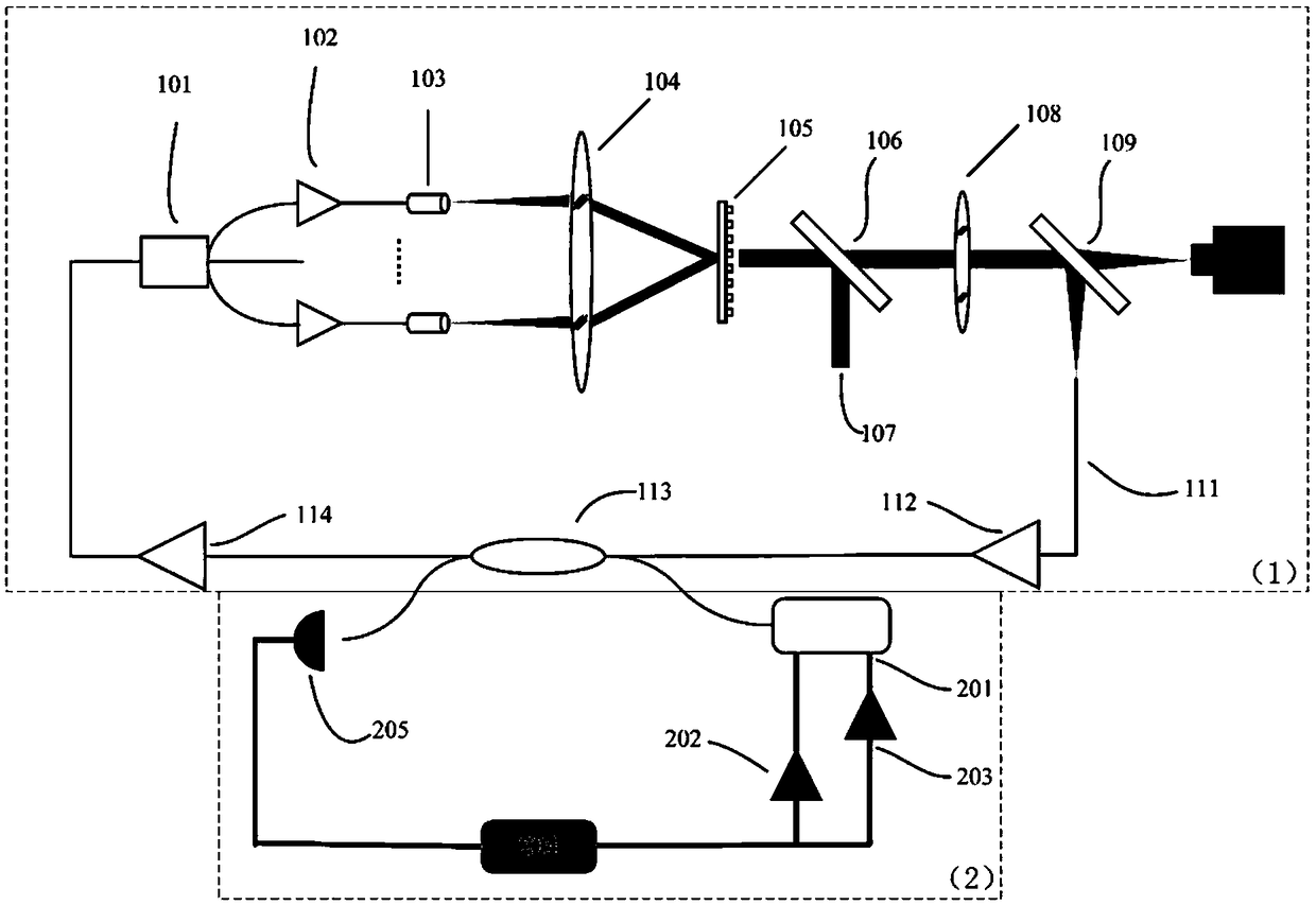
[0026] figure 1 It is a schematic diagram of the DOE coherent synthesis light source based on the ring cavity active optical feedback of the present invention. It can be seen from the figure that the present invention is based on the laser light source coherently combined by the diffractive optical element of the active optical feedback of the ring cavity, including the passive ring cavity 1 of the full optical feedback and the active photoelectric feedback loop 2,

[0027] The passive annular cavity 1 of the all-optical feedback includes sequentially connected 1×N fiber beam splitter 101, and the 1×N fiber beam splitter 101 divides the incident light into N paths, and passes through N-way fiber amplifiers 102, corresponding The output end cap array 103 and the first collimating...


PUM


Abstract

The invention relates to a laser light source of diffractive optical element coherent synthesis based on active optical feedback of a ring cavity. The laser light source mainly comprises an all-optical-feedback type passive annular cavity and a two-stage active control optical loop with different tuning ranges. The laser light source is characterized in that multi-path narrow-linewidth fiber laserdevices are combined into one beam of high-energy laser for output by means of all-optical feedback common-aperture coherent synthesis; after adding of an active control type feedback loop, the initial main oscillation seed wavelength is ensured to be consistent with the central wavelength of a feedback cavity mode, so that the output line width of the synthetic laser is further narrowed, the phase noises are reduced, the interference on the ring cavity by the external environment is reduced, and the phase locking effect is stabilized. According to the invention, defects of low synthesis efficiency, strong phase noises and poor phase locking effect of the traditional passive coherent synthesis system are overcome; the high stability and safety of the synthetic system are kept; the scale of the array is extended; and the brightness of the narrow-linewidth output laser is enhanced. An effective technical path is provided for realizing high-power and good-beam-quality expansion of the fiber laser device.

Description

technical field [0001] The invention relates to a laser light source, in particular to a laser light source coherently combined by a diffractive optical element (DOE) based on the active optical feedback of a ring cavity. Background technique [0002] Fiber lasers have the advantages of simple and compact structure, convenient thermal management, high energy conversion efficiency, stable and reliable performance, and good beam quality, and have been widely used in the field of high-power laser technology. At present, the output power of single-mode fiber lasers has exceeded 10,000 watts. However, limited by factors such as thermal effects, nonlinear effects, mode instability, and end-face damage, there is a theoretical limit to the output power of a single fiber laser. [0003] In order to improve the output power of fiber laser sources with narrow linewidth and low phase noise, coherent beam combining has been proposed and studied deeply, and has become one of the most imp...

Claims


Application Information

Patent Timeline
IPC IPC(8): H01S3/13H01S3/10H01S3/083G02B27/42
CPCG02B27/4266H01S3/083H01S3/10015H01S3/10023H01S3/1305
Inventor 周军柏刚沈辉杨依枫何兵牛夏夏刘美忠
Owner SHANGHAI INST OF OPTICS & FINE MECHANICS CHINESE ACAD OF SCI
Why Eureka
Try Eureka