Accelerating tube and linear accelerator

A technology of accelerating tube and accelerating cavity, which is applied in linear accelerators, accelerators, electrical components, etc., can solve the problems of poor working stability and easy damage to the structural stability of the accelerating tube, and achieve the effect of improving stability.

Active Publication Date: 2019-03-19
SHANGHAI UNITED IMAGING HEALTHCARE
View PDF14 Cites 1 Cited by
  • Summary
  • Abstract
  • Description
  • Claims
  • Application Information

AI Technical Summary

Problems solved by technology

However, the solution of this prior art easily destroys the stability of the accelerating tube structure
Therefore, the existing accelerating tube has the problem of poor working stability

Method used


Image

  • Accelerating tube and linear accelerator
  • Accelerating tube and linear accelerator
  • Accelerating tube and linear accelerator

Examples


Embodiment Construction

[0026] The present invention will be further described in detail below in conjunction with the accompanying drawings and embodiments. It should be understood that the specific embodiments described here are only used to explain the present invention, but not to limit the present invention. In addition, it should be noted that, for the convenience of description, only some structures related to the present invention are shown in the drawings but not all structures.

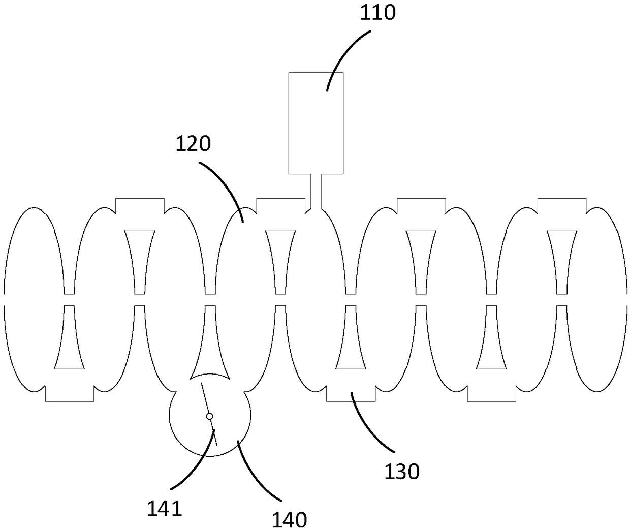
[0027] figure 1 It is a structural schematic diagram of an existing accelerating tube. see figure 1 , the accelerating tube includes a waveguide 110 , multiple accelerating cavities 120 and multiple coupling cavities 130 . The waveguide 110 is coupled to the accelerating cavities 120 , and guides electromagnetic waves of fixed power generated by the microwave source to the multiple accelerating cavities 120 . A plurality of accelerating cavities 120 are arranged in a straight line array and communicated through...


PUM


Abstract

The invention discloses an accelerating tube and a linear accelerator, and the accelerating tube comprises a waveguide and a plurality of accelerating cavities. The waveguide is coupled to one accelerating cavity. The accelerating tube also comprises a coupling degree adjustment device which is coupled to the waveguide, and is used for adjusting the coupling degree of the waveguide and the accelerating cavities. According to the embodiment of the invention, the original accelerating cavity structure is not changed, and only the electromagnetic waves guided to the accelerating cavities are adjusted, and there is no need to adjust the electromagnetic waves in the accelerating cavities. Therefore, the stability of the accelerating cavity structure cannot be damaged, and the work stability ofthe accelerating tube is improved.

Description

technical field [0001] Embodiments of the present invention relate to the technical field of medical equipment, in particular to an accelerating tube and a linear accelerator. Background technique [0002] Medical linear accelerator refers to an acceleration device that uses microwave electromagnetic fields to accelerate electron beams and has linear motion orbits. Electron beams accelerate in electromagnetic fields and gain energy, and bombard metal targets to generate X-rays. It has high dose rate, short irradiation time, and Large field, dose uniformity and small penumbra. [0003] In the prior art, usually an accelerator only works optimally at one energy. When multiple levels of energy are required (for example, imaging energy and treatment energy), it is necessary to change the output power of the microwave source, so that the energy of the output electrons can be selected. 15MeV, 10MeV, 1.5MeV and 1.5MeV or less. However, the adjustment of different energy levels me...

Claims


Application Information

Patent Timeline
Patent Type & Authority Applications(China)
IPC IPC(8): H05H7/22H05H9/00
CPCH05H7/22H05H9/00
Inventor 程鹏宋瑞英
Owner SHANGHAI UNITED IMAGING HEALTHCARE
Why Eureka
Try Eureka