Anesthetic spraying air pipe structure

A technology of anesthetics and trachea, which is applied in the field of anesthetic spraying trachea structure, can solve problems such as coughing and loss of anesthetic efficacy, and achieve the effects of reducing pain, facilitating rescue and treatment, and facilitating treatment

Pending Publication Date: 2019-03-22
SHANGHAI PULMONARY HOSPITAL
View PDF24 Cites 1 Cited by
  • Summary
  • Abstract
  • Description
  • Claims
  • Application Information

AI Technical Summary

Problems solved by technology

[0003] During tracheal intubation, it is generally necessary to perform local anesthesia on the patient's throat and glottis to ensure that patients with sensitive throat and glottis can cooperate to allow the smooth insertion of the tracheal tube. Over time, the effect of anesthetics gradually loses, the patient enters the anesthesia recovery period, and the throat regains consciousness. Due to the insertion of the endotracheal tube, the patient will have symptoms of intolerance such as choking and coughing, which will make the patient feel more painful

Method used


Image

  • Anesthetic spraying air pipe structure
  • Anesthetic spraying air pipe structure
  • Anesthetic spraying air pipe structure

Examples


Embodiment 1

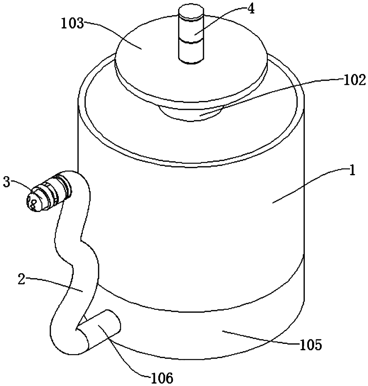
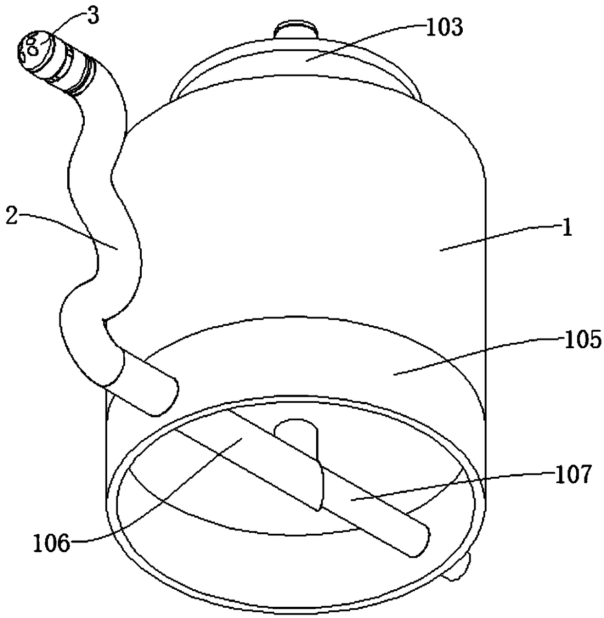
[0033] refer to Figure 1-5 , an anesthetic drug spraying trachea structure, comprising a drug injection cylinder 1, a first drug spraying trachea 106 and a second drug spraying trachea 2, the outer wall of the drug injection cylinder 1 is connected with a first concave hole, and the bottom of the drug injection cylinder 1 is dug with a second Concave hole, the first spraying gas pipe 106 communicates with the second concave hole, the cylinder 105 is connected to the bottom of the injection cartridge 1, the first spraying gas pipe 106 passes through the cylinder 105 and communicates with the second spraying gas pipe 2, Both the first medicine spraying air pipe 106 and the second medicine spraying air pipe 2 are connected with a breathing air pipe 107, and the end of the breathing air pipe 107 away from the first medicine spraying air pipe 106 passes through the cylinder 105 and extends outward; The structure is placed in the position where it needs to be used, and the cylinder...

Embodiment 2

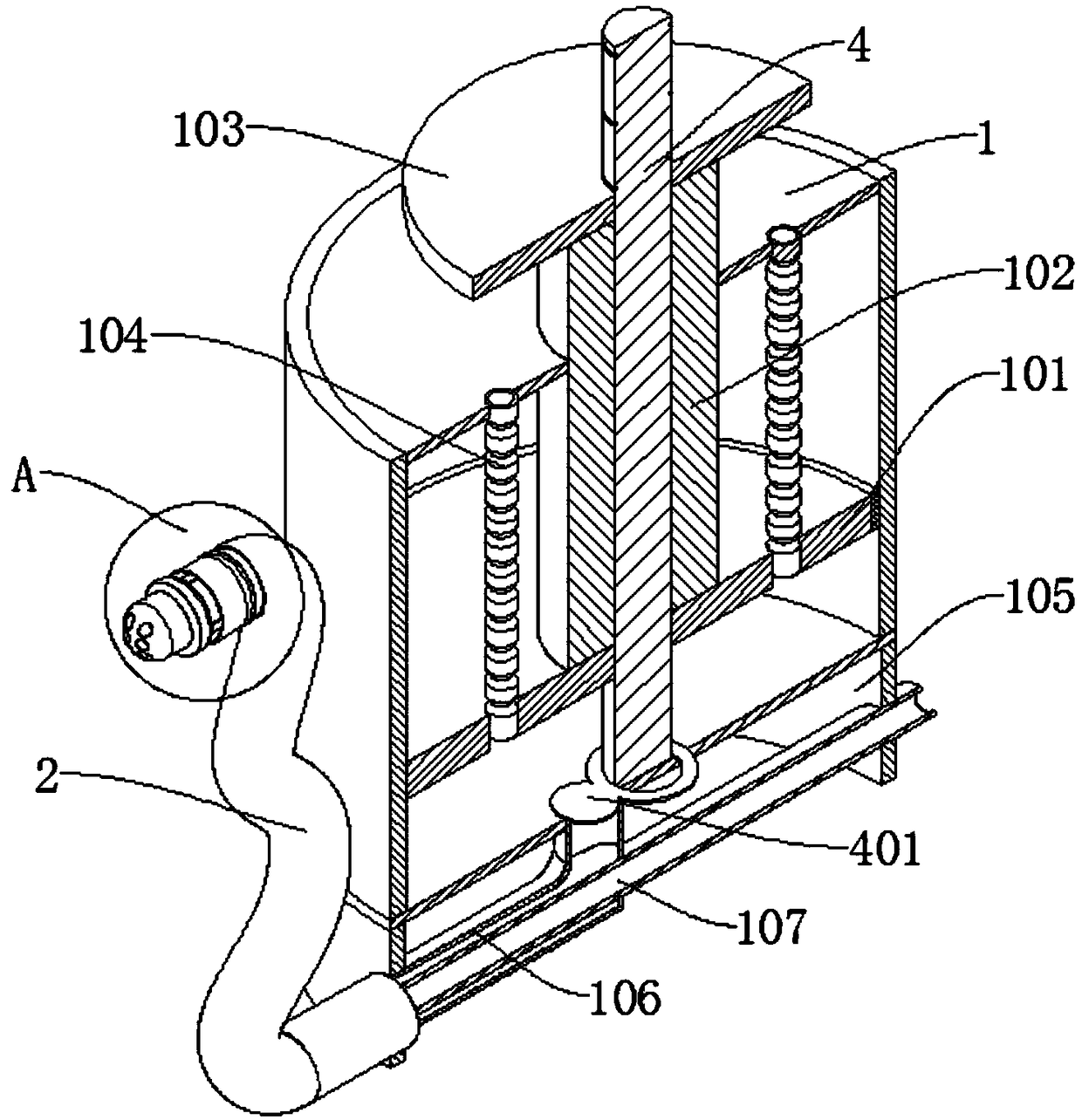
[0035] refer to Figure 1-4 , an anesthetic spraying trachea structure, which is basically the same as that of Embodiment 1. Further, the inner wall of the injection cylinder 1 is connected with a piston 101, the outer wall of the piston 101 is connected with a push rod 102, and the end of the push rod 102 far away from the piston 101 is connected with a Push plate 103; by pushing the push plate 103, the push plate 103 pushes the push rod 102 to move, so that the push rod 102 pushes the piston 101 to move, so that the piston 101 pushes the anesthetic liquid in the injection cylinder 1 to pass through the first The first medicine spraying air pipe 106 and the second medicine spraying air pipe 2 are sprayed to the patient's throat to anesthetize the patient, thereby reducing pain and facilitating treatment.

[0036] The outer wall of the piston 101 is connected with a sealing ring; the sealing ring can seal the piston 101 and the inner wall of the injection cylinder 1 so that th...

Embodiment 3

[0039] refer to Figure 1-4 , a structure of an anesthetic spraying trachea, which is basically the same as that of Embodiment 1. Furthermore, the inner wall of the bottom of the injection cylinder 1 is rotatably connected to a fixed column 4, and the piston 101, push rod 102 and push plate 103 are all slidably connected to the fixed column. 4, the outer wall of the fixed column 4 is provided with a scale; by pushing the push plate 103, the push rod 102 and the piston 101 are driven to slide on the outer wall of the fixed column 4, and the sealing between the piston 101 and the fixed column 4 is arranged so that the anesthetic liquid will not Flow out from the gap, and the outer wall of the fixed column 4 is provided with scales, so that the height of the push plate 103 can be controlled, so as to quantify the injected anesthetic liquid, and avoid excessive injection and cause harm to the patient.

[0040] The outer wall of the fixed column 4 is connected with a baffle 401, th...


PUM


Abstract

The invention discloses an anesthetic spraying air pipe structure, and belongs to the technical field of anesthetic spraying air pipes. The anesthetic spraying air pipe structure comprises a medicineinjection barrel, a first medicine spraying air pipe and a second medicine spraying air pipe, wherein a first concave hole is connected to the outer wall of the medicine injection barrel; the bottom of the medicine injection barrel is cut with a second concave hole; the first medicine spraying air pipe is communicated with the second concave hole; the bottom of the medicine injection barrel is connected with a cylinder; the first medicine spraying air pipe penetrates through the cylinder and is communicated with the second medicine spraying pipe; a breathing air pipe is connected to the firstmedicine spraying pipe and the second medicine spraying pipe; and one end of the breathing air pipe far away from the first medicine spraying pipe penetrates through the cylinder and extends outwards.The structure can conveniently spray the anesthetic liquid to a patient, and the patient is prevented from suffering from tube intolerance symptoms such as cough and the like caused by the fact thatthe drug effect of the anesthetic liquid gradually loses during the treatment of the patient, so that the pain of the patient is reduced.

Description

technical field [0001] The invention relates to the technical field of anesthetic spraying trachea, in particular to a structure for anesthetic spraying trachea. Background technique [0002] Endotracheal intubation is a method of inserting a special endotracheal tube through the oral cavity or nasal cavity and into the trachea or bronchi through the glottis to provide the best conditions for unobstructed airway, ventilation and oxygen supply, and airway suction. important measures. [0003] During tracheal intubation, it is generally necessary to perform local anesthesia on the patient's throat and glottis to ensure that patients with sensitive throat and glottis can cooperate to allow the smooth insertion of the tracheal tube. Over time, the effect of anesthetics gradually loses, and the patient enters the anesthesia recovery period, and the sensation in the throat is restored. Due to the insertion of the endotracheal tube, the patient will have symptoms of intolerance su...

Claims


Application Information

Patent Timeline
Patent Type & Authority Applications(China)
IPC IPC(8): A61M19/00
CPCA61M19/00A61M2210/1046A61M2210/005
Inventor 李春李华
Owner SHANGHAI PULMONARY HOSPITAL
Why Eureka
Try Eureka