Eureka AIR delivers breakthrough ideas for toughest innovation challenges, trusted by R&D personnel around the world.

Cycloid gear machining fixture

A cycloidal gear and fixture technology, which is applied in the direction of manufacturing tools, metal processing equipment, gear tooth manufacturing devices, etc., can solve the problems of high production cost, difficult to achieve, high precision, etc., and achieve high clamping precision, low precision requirements, good The effect of precision

Active Publication Date: 2019-03-22
NINGBO ZHONGDA LEADER TRANSMISSION EQUIP
View PDF11 Cites 1 Cited by
  • Summary
  • Abstract
  • Description
  • Claims
  • Application Information

AI Technical Summary

Problems solved by technology

[0004] However, the epicycloidal teeth are processed by adopting the method of internal bearing hole positioning. If the machining accuracy requirement is 0.01mm, based on the concentricity requirement of 0.005mm, the diameter of the bearing hole distribution is A, and the diameter of the pitch circle of the cycloid is D, then The concentricity requirement of the fixture is (A / D)*0.005, that is to say, the comprehensive requirement for installation needs to be around 0.0025mm, and the precision of the fixture around 0.0025mm is too high, which is not only difficult to achieve, but also leads to its production The cost is too high and the life is too short

Method used


Image

  • Cycloid gear machining fixture
  • Cycloid gear machining fixture
  • Cycloid gear machining fixture

Examples


Embodiment 1

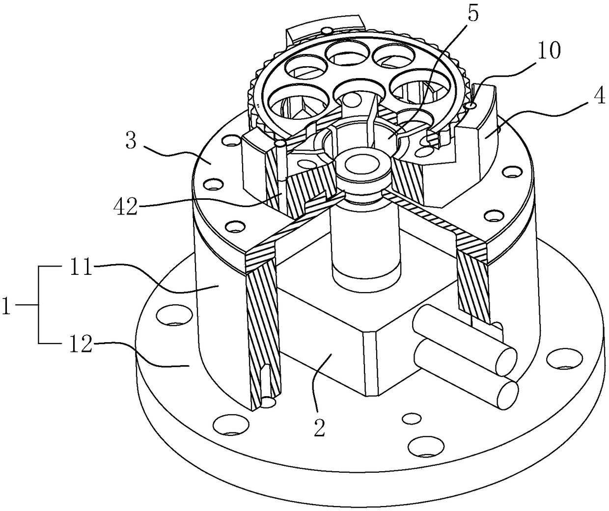
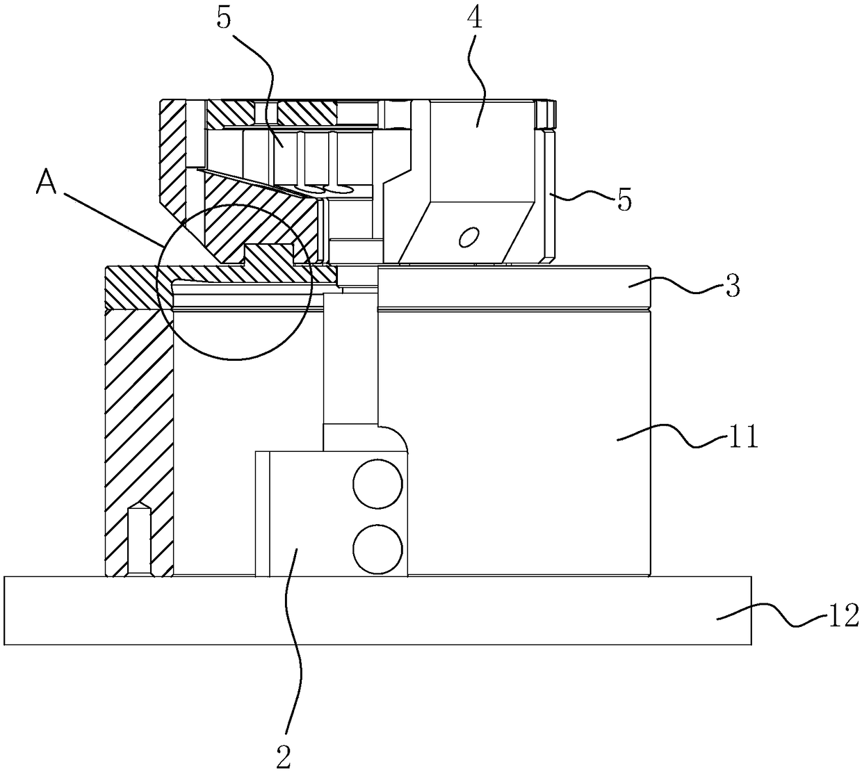
[0045] Embodiment 1: A kind of cycloidal gear machining fixture, such as figure 1 with figure 2 As shown, it includes a housing 1 , a supporting claw 5 , a clamping claw 4 , a diaphragm 3 and a driving element 2 .

[0046] The casing 1 includes a chassis 11 and a casing 12 , the casing 12 is in the shape of a cylinder with two ends open, and is mounted on the chassis 11 by bolts.

[0047] The drive element 2 can be a hydraulic cylinder or a pneumatic cylinder, preferably a hydraulic cylinder. The driving element 2 is fixedly installed on the chassis 11 and located in the casing 12 .

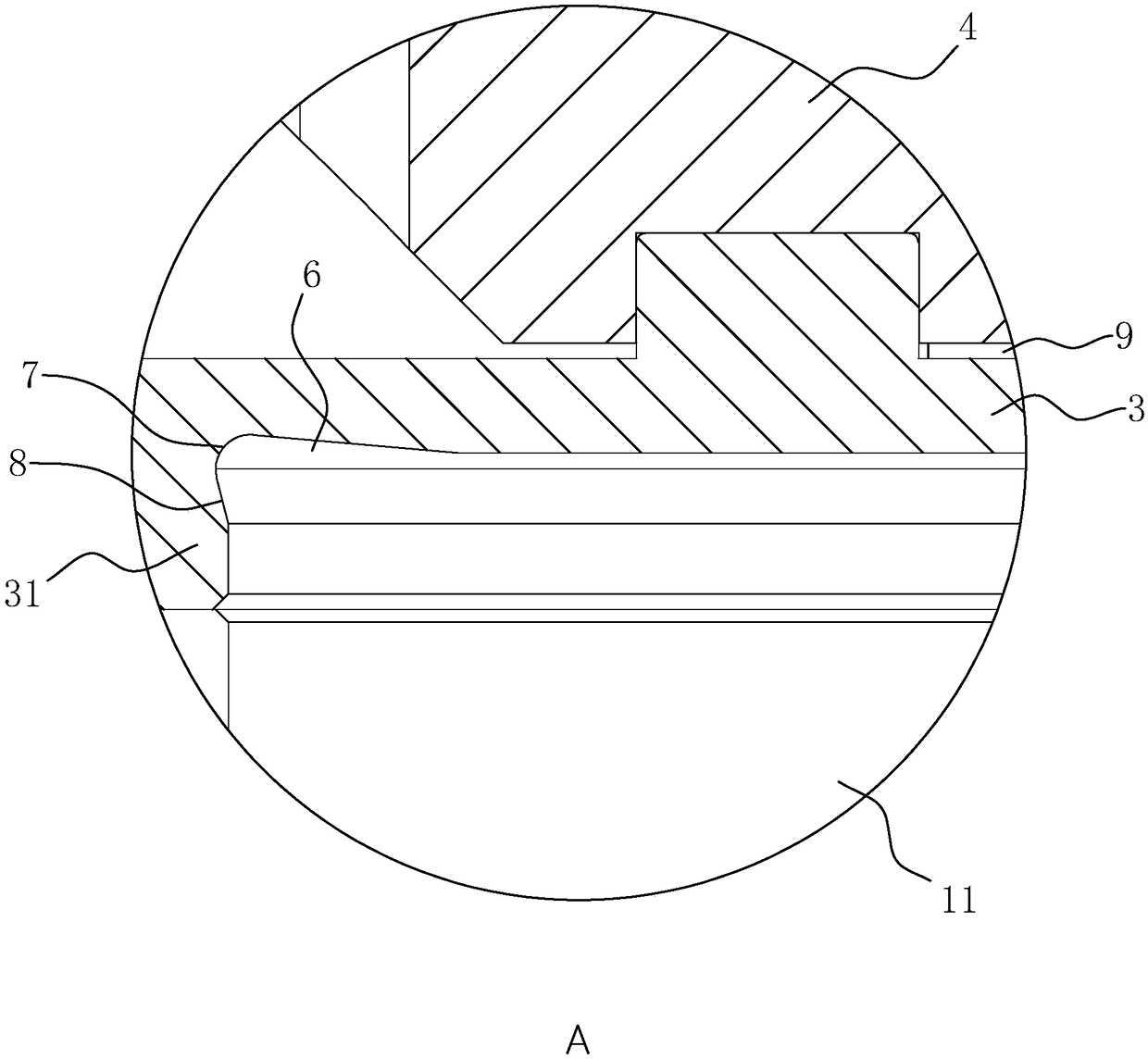
[0048] Diaphragm 3 is made of elastic steel, and a mounting part 31 is integrally provided around the edge of diaphragm 3 . The thickness of mounting part 31 is greater than that of diaphragm 3 , and the mounting part 31 is connected to housing 12 by bolts. A through hole is provided in the middle of the diaphragm 3 , and the piston rod of the driving element 2 is fixedly connected with the d...

Embodiment 2

[0056] Embodiment 2: as Figure 7 As shown, the difference from Embodiment 1 is that the bottom end faces of the claws 5 and 4 are placed against the end face of the diaphragm 3, and the maximum distance between the bottom end face of the jaw 4 and the center of the diaphragm 3 is less than the guide The minimum distance between the deformation part 6 and the center of the diaphragm 3 .


PUM


Abstract

The invention discloses a cycloid gear machining fixture comprising a holding claw, a clamping claw, a diaphragm and a driving element. The holding claw is used to provide a gear placing platform, theclamping claw is used to clamp a gear placed on the holding claw, the diaphragm is fixedly arranged on a shell and is used to mount the clamping claw and the holding claw, the clamping claw is controlled to close for clamping or open for relieving clamping through shape change of the diaphragm, and the driving element is connected with the diaphragm and is used to supply shape change power for the diaphragm. When the fixture is in use, a cycloid gear is placed on the placing platform formed by the holding claw, and then the driving element is launched and the diaphragm is pulled for shape change to drive the clamping claw to clamp the cycloid gear; or the driving element is launched first to push the diaphragm to open the clamping claw, then the cycloid gear is placed on the placing platform formed by the holding claw, and then the diaphragm is reset by controlling the driving element to achieve the clamping.

Description

technical field [0001] The invention relates to the technical field of a gear processing jig, in particular to a cycloidal gear processing jig. Background technique [0002] Cycloidal gears are a general term for cylindrical gears with tooth profiles of various cycloids or equidistant curves. It is best for each piece to be the same, interchangeable and universal, and do not use one-to-one processing. [0003] Cycloidal gears have phase requirements for the outer cycloidal teeth and the inner bearing holes, as well as precise positioning requirements. The phase between the two epicycloidal teeth and the center line of the bearing hole must be within ±0.01º, and the concentricity between the bearing hole and the epicycloidal teeth must be within 0.005mm. The precision requirements are very high, which is difficult to achieve with ordinary chucks. The current processing The way is to use two sets of one set to grind the epicycloid teeth at the same time to ensure the phase re...

Claims


Application Information

Patent Timeline
Patent Type & Authority Applications(China)
IPC IPC(8): B23F23/06
CPCB23F23/06
Inventor 罗利敏罗跃冲岑国建
Owner NINGBO ZHONGDA LEADER TRANSMISSION EQUIP
Why Eureka
Eureka Blog
Learn More