Impeller high-inclination-angle laser oblique impact laser beam space energy distribution compensation method

A technology of spatial energy and distribution compensation, applied in special data processing applications, instruments, electrical digital data processing, etc., can solve problems such as complex impeller structure, difficulty in laser shock strengthening treatment, and easy fracture

Active Publication Date: 2019-03-22
GUANGDONG LASER PEENING TECH CO LTD
View PDF8 Cites 11 Cited by
  • Summary
  • Abstract
  • Description
  • Claims
  • Application Information

AI Technical Summary

Problems solved by technology

However, in the actual working process, problems such as fracture are prone to occur at the root of the blade, and the use of laser shock strengthening technology can solve these problems well and improve the service life of the impeller
[0004] However, the overall structure of the impeller is complex, especially the impeller with a large inclination angle

Method used


Image

  • Impeller high-inclination-angle laser oblique impact laser beam space energy distribution compensation method
  • Impeller high-inclination-angle laser oblique impact laser beam space energy distribution compensation method
  • Impeller high-inclination-angle laser oblique impact laser beam space energy distribution compensation method

Examples


Embodiment Construction

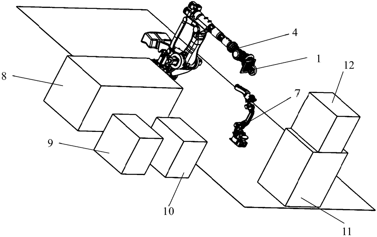
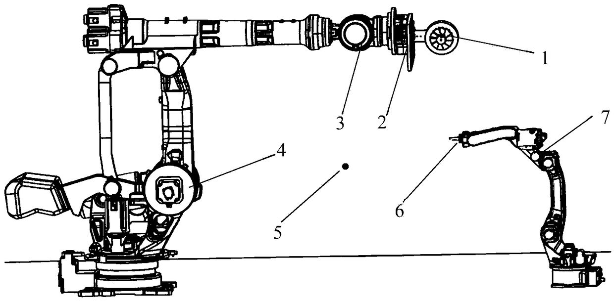
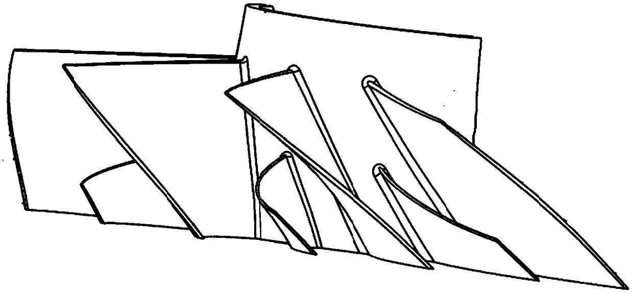
[0027] Whether the method in this embodiment is a simulation or an actual laser shock peening process, the following arrangement can be used to carry out. Such as figure 1 and figure 2 As shown, the impeller 1 (part) is mounted on a fixture 2 , which is assembled on a manipulator 3 , which may be part of a gripping robot 4 . The opposite side of the clamping robot 4 is a water-coating robot 7, and the mechanical arm of the water-coating robot 7 is provided with a water sprayer 6. The output of the laser generator 8 faces the impeller 1 . The laser power supply cabinet 9 and the laser control cabinet 10 are close to the laser generator 8 and supply power and control it; a laser peening system control system 12, which is used to control the laser peening system arranged at the output end of the laser generator; a robot control cabinet 11 It is used to control the action of clamping robot 4 and water coating robot 7. The impeller parts to be strengthened such as Figure 3 t...


PUM


Abstract

The invention discloses an impeller high-inclination-angle laser oblique impact laser beam space energy distribution compensation method, and belongs to the field of laser impact enhancement. The method comprises following steps that a part model and a clamp model are guided into robot simulation software, the robot simulation software is used for adopting the discrete point off-line programming manner for writing the motion track of a clamping robot during laser impact enhancement; c, according to the track parameters, differences of overlap rates of different portions and space coordinates of a laser beam on each point in the offline programming, the laser power density parameter of each point is determined through the vector formula; d, the track parameter of the clamping robot and theimpact enhancement parameter of a laser device can be continuously modified; e, the motion track program of the clamping robot in the simulation software is guided into the robot system, and accordingto the preset state in the simulation software, the actual part is subjected to laser impact enhancement treatment. The problem about interference between blades of a small-space large-inclination-angle impeller and the laser beam can be solved.

Description

technical field [0001] The invention relates to the technical field of laser shock strengthening, in particular to a compensation method for spatial energy distribution of a laser beam obliquely shocking an impeller with a large inclination angle and a stilling pipe. Background technique; [0002] Laser shock strengthening technology is a high-tech technology that uses plasma shock waves generated by strong laser beams to improve the fatigue resistance, wear resistance and corrosion resistance of metal materials. It has outstanding advantages such as non-contact, no heat-affected zone, strong controllability and remarkable strengthening effect. [0003] The aeroengine impeller is a key part of the aeroengine. The impeller is a new structural part designed to meet the high-performance aeroengine. It integrates the engine rotor blade and the disc, eliminating the tenon, tenon and groove in the traditional connection. tightening device, etc., reduce the structural weight and t...

Claims


Application Information

Patent Timeline
IPC IPC(8): C21D10/00G06F17/50
CPCC21D10/005G06F30/20
Inventor 张永康刘俊吴清源
Owner GUANGDONG LASER PEENING TECH CO LTD
Why Eureka
Try Eureka