System and method for testing reflectivity of wave-absorbing material

A testing system and wave-absorbing material technology, which is applied in the direction of material analysis, material analysis, and measuring devices using microwave means, can solve the problems of large gear span, short service life, and easy gear jamming, etc., and achieve easy manufacturing and assembly , Stable and reliable work, high adjustment accuracy

Active Publication Date: 2019-03-22
CHANGSHA JINGYOU NEW MATERIAL TECH CO LTD
View PDF6 Cites 5 Cited by
  • Summary
  • Abstract
  • Description
  • Claims
  • Application Information

AI Technical Summary

Problems solved by technology

There are two main methods for the existing radar reflectivity test system to measure the reflectivity under different incident angles: one is to use electric arc gears to drive the antenna to rotate to realize the measurement of reflectivity at different angles, but the gear span used in this method Large, it puts forward very strict requirements on the accuracy and rigidity of the gears, and there are problems such as difficulty in manufacturing and installation, easy jamming of the gears, high cost, and short service life; the second is to use small-span gears to drive "7 "The glyph cantilever drives the antenna to rotate. Although the cost of this method is low, the cantilever structure is easy to cause the antenna to shake, and it is easy to cause the gear to deform after a long time of use.

Method used


Image

  • System and method for testing reflectivity of wave-absorbing material
  • System and method for testing reflectivity of wave-absorbing material
  • System and method for testing reflectivity of wave-absorbing material

Examples


Embodiment Construction

[0031] The present invention will be described in further detail below in conjunction with the accompanying drawings and specific embodiments.

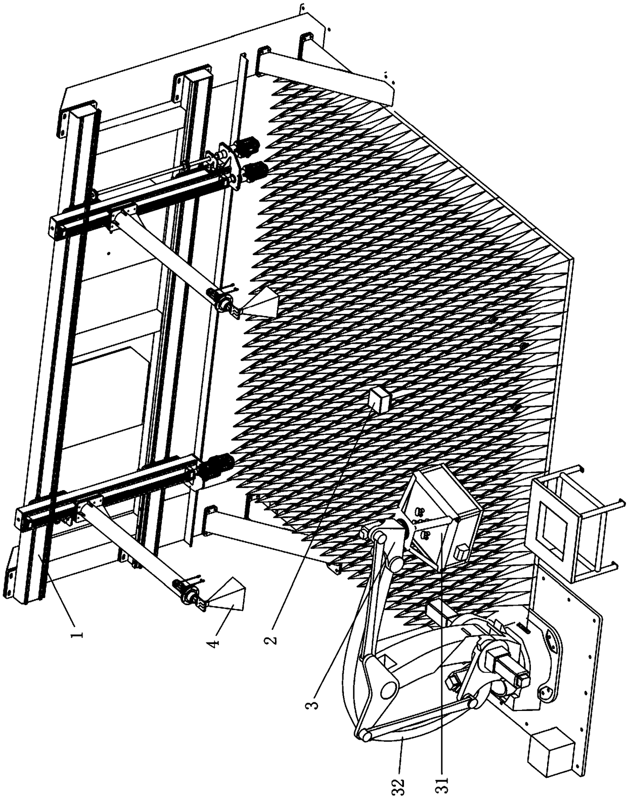
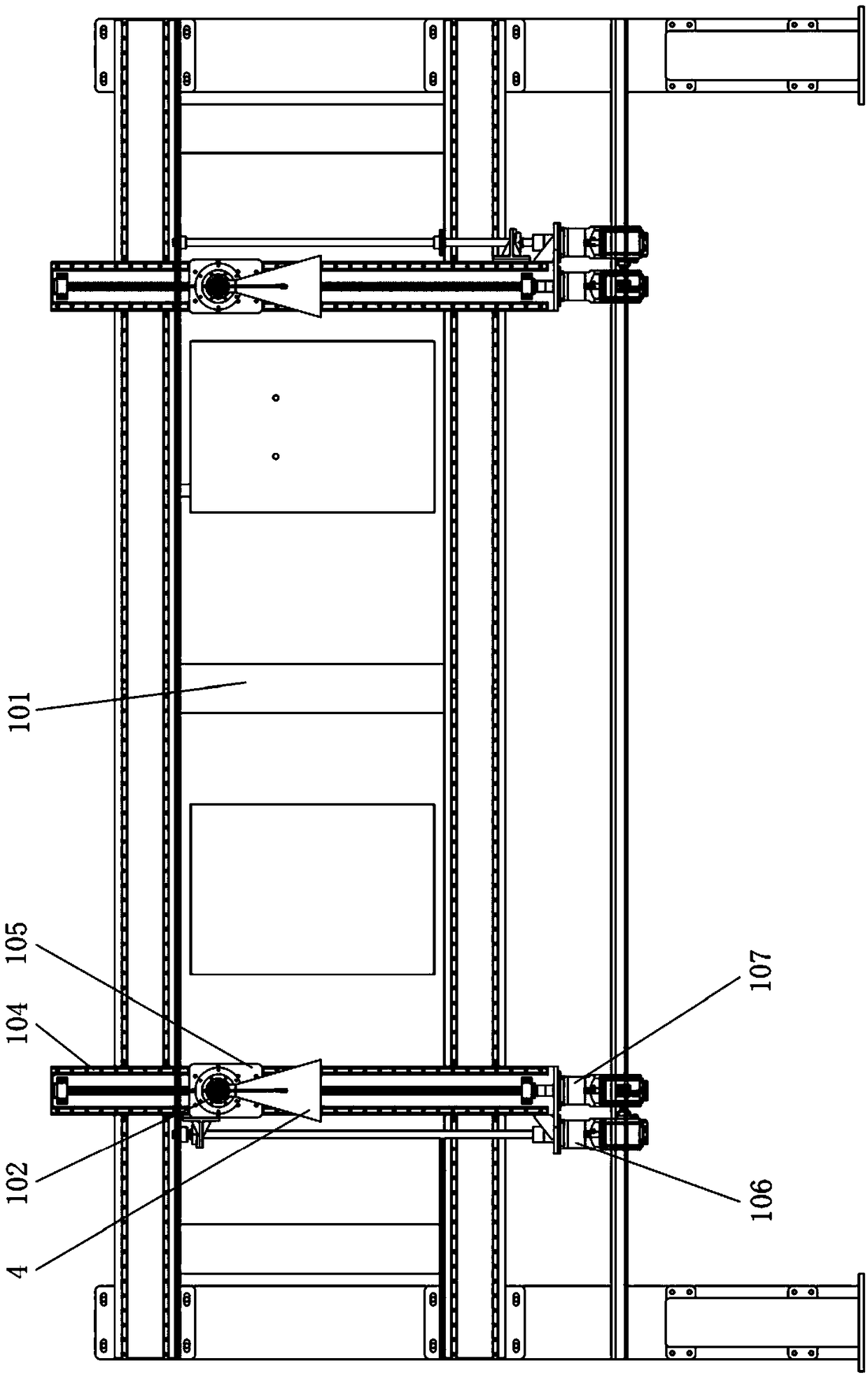
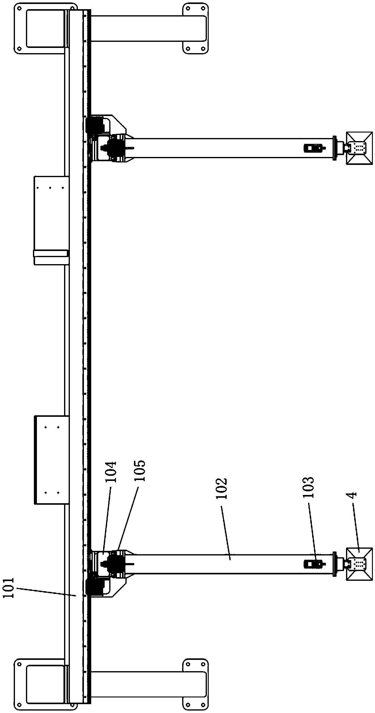
[0032] Such as Figure 1 to Figure 4 As shown, the reflectivity testing system of the absorbing material in this embodiment includes an incident angle adjustment device 1, a workpiece support platform 2 and a direct beam antenna 4, the workpiece support platform 2 is fixedly arranged, and the incident angle adjustment device 1 includes a bracket 101, a cantilever 102 and a rotary drive 103, the cantilever 102 is installed on the bracket 101 through a vertical automatic displacement component and can be driven to move in a vertical plane by the vertical automatic displacement component, the rotary drive 103 is installed on the cantilever 102, and the antenna 4 is connected with the driving end of the rotary driving member 103 and can be driven by the rotary driving member 103 to rotate around the horizontal axis. The incident angle ad...


PUM


Abstract

The invention discloses a system and method for testing reflectivity of a wave-absorbing material. The reflectivity testing system comprises an incident angle adjusting device, a workpiece bearing platform and a correlation antenna, wherein the incident angle adjusting device comprises a bracket, a cantilever and a rotary drive part; the cantilever is mounted on the bracket by virtue of a verticalsurface automatic displacement component and can be driven to move in a vertical plane by the vertical surface automatic displacement component; the rotary drive part is mounted on the cantilever; the correlation antenna is connected with a drive end of the rotary drive part and can be driven to rotate around a horizontal axis by the rotary drive part. The testing method comprises the following steps: driving a heating furnace to move by a manipulator, enabling the workpiece bearing platform to stretch into a furnace mouth, opening the heating furnace to heat to-be-tested sample plates and maintain the temperature, driving the heating furnace to move by the manipulator so as to enable the heating furnace to be far away from the workpiece bearing platform, and opening the correlation antenna to test the reflectivity. The system disclosed by the invention has the advantages of being simple in structure, low in cost, stable and reliable in operation, high in regulation precision, long inservice life, easy to manufacture and assemble and the like.

Description

technical field [0001] The invention relates to the technical field of microwave testing equipment, in particular to a reflectivity testing system and testing method of a microwave-absorbing material. Background technique [0002] Radar absorbing materials (referred to as absorbing materials) are widely used in civil and military fields, and radar reflectivity (referred to as reflectivity) is an important index parameter used to evaluate the absorbing performance of absorbing materials. The reflectivity measurement technology of absorbing materials at room temperature is relatively mature and has been widely used. However, as engines, high-speed aircraft and high-power microwave devices increase the temperature resistance of absorbing materials, radar The requirements of the reflectivity test system are also getting higher and higher. [0003] At present, the high-temperature reflectivity test system mainly adopts the method of bottom heating, that is, the heating element i...

Claims


Application Information

Patent Timeline
Patent Type & Authority Applications(China)
IPC IPC(8): G01N22/00
CPCG01N22/00
Inventor 易伟刘小康杨闪剑袁铁朱立军吴拥军易麦儿
Owner CHANGSHA JINGYOU NEW MATERIAL TECH CO LTD
Why Eureka
Try Eureka