Display panel, array substrate, thin film transistor and manufacturing method of thin film transistor

A technology for thin film transistors and manufacturing methods, which is applied to transistors, semiconductor/solid-state device manufacturing, electric solid-state devices, etc., can solve the problems of large loss of photoresist, difficult process, and residual photoresist, so as to shorten the etching time. Time, improve product yield, reduce the effect of process difficulty

Active Publication Date: 2019-03-22
HEFEI XINSHENG OPTOELECTRONICS TECH CO LTD +1
View PDF4 Cites 13 Cited by
  • Summary
  • Abstract
  • Description
  • Claims
  • Application Information

AI Technical Summary

Problems solved by technology

[0003] However, the thickness of the dielectric layer and the buffer layer is relatively large, and the thickness after stacking is even greater, so that the process of opening the contact hole for the stacked dielectric layer and buffer layer is relatively difficult, and it takes a long time. Etching will cause a very large loss of photoresist, and make the photoresist prone to denaturation, which will cause the photoresist to be peeled off in the removal process, resulting in photoresist residue, which will have a negative impact on the subsequent process. Lower panel yield and display quality

Method used


Image

  • Display panel, array substrate, thin film transistor and manufacturing method of thin film transistor
  • Display panel, array substrate, thin film transistor and manufacturing method of thin film transistor
  • Display panel, array substrate, thin film transistor and manufacturing method of thin film transistor

Examples


Embodiment Construction

[0048] Example embodiments will now be described more fully with reference to the accompanying drawings. Example embodiments may, however, be embodied in many forms and should not be construed as limited to the embodiments set forth herein; rather, these embodiments are provided so that this disclosure will be thorough and complete, and will fully convey the concept of example embodiments to those skilled in the art. The same reference numerals in the drawings denote the same or similar structures, and thus their detailed descriptions will be omitted.

[0049] Although relative terms such as "upper" and "lower" are used in this specification to describe the relative relationship of one component of an icon to another component, these terms are used in this specification only for convenience, for example, according to the description in the accompanying drawings directions for the example described above. It will be appreciated that if the illustrated device is turned over so...


PUM


Abstract

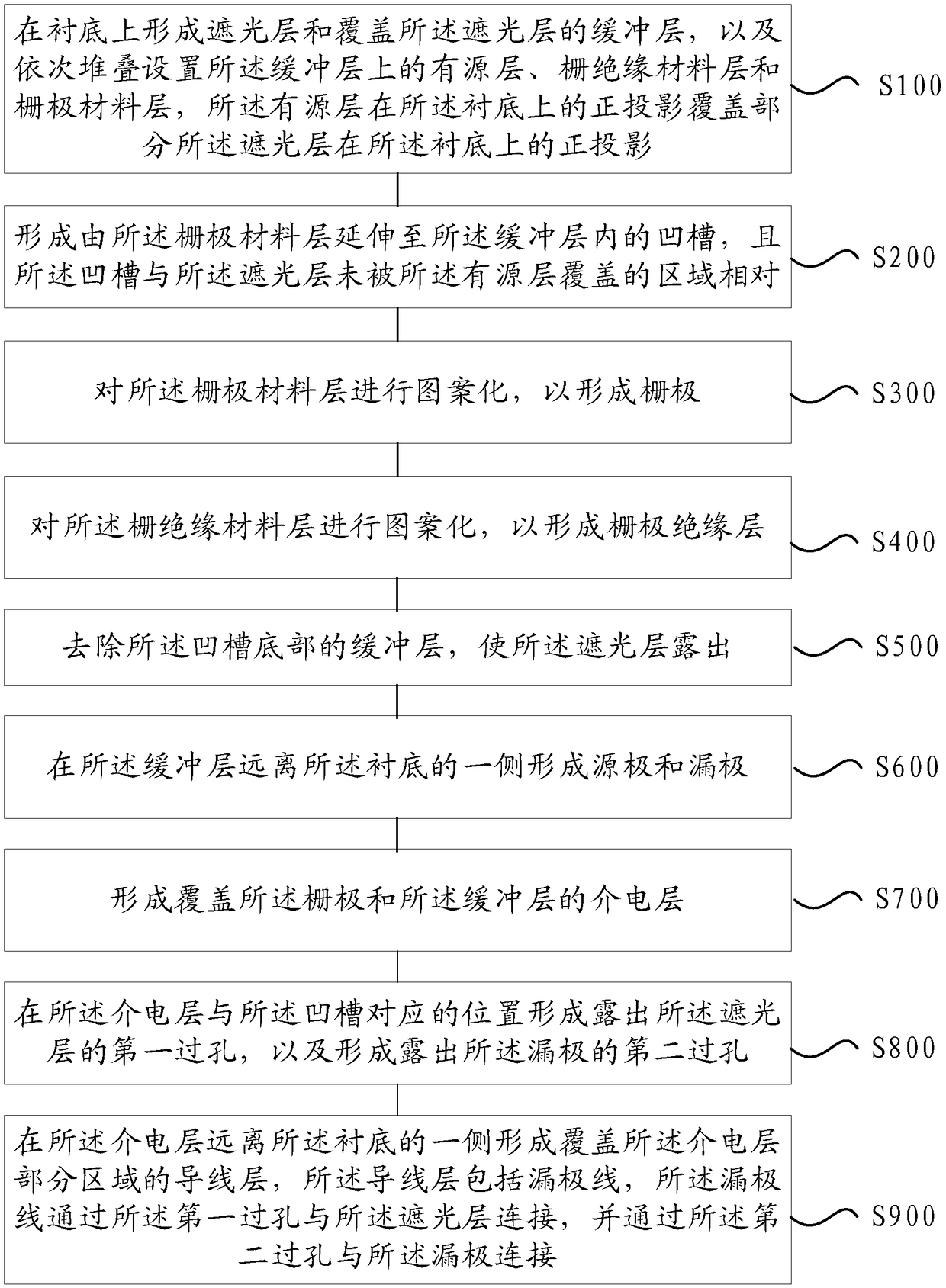
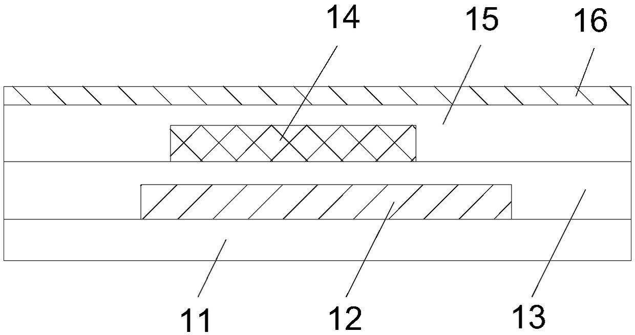
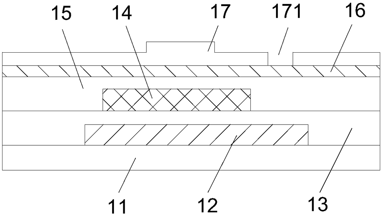
The present invention relates to a manufacturing method of a thin film transistor, a thin film transistor, an array substrate, and a display panel. The manufacturing method includes the following steps that: a light shielding layer and a buffer layer covering the light shielding layer are formed on a substrate, and an active layer, a gate insulating material layer, and a gate material layer sequentially stacked on the buffer layer are also formed, the orthographic projection of the active layer on the substrate covers the orthographic projection of a portion of the light shielding layer on thesubstrate; a groove extending from the gate material layer into the buffer layer is formed, and the groove is opposite to a region of the light shielding layer which is not covered with the active layer; patterning is performed on the gate material layer, so that a gate is formed; patterning is performed on the gate insulating material layer, so that a gate insulating layer is formed; the bufferlayer at the bottom of the groove is removed, so that the light shielding layer can be exposed; a source and a drain are formed on a surface of the buffer layer, wherein the surface of the buffer layer is away from the substrate; a dielectric layer covering the gate and the buffer layer is formed; a first via hole exposing the light shielding layer is formed at a position of the dielectric layer which is corresponding to the groove, and a second via hole exposing the drain is also formed in the dielectric layer.

Description

technical field [0001] The present disclosure relates to the field of display technology, in particular, to a manufacturing method of a thin film transistor, a thin film transistor, an array substrate and a display panel. Background technique [0002] Currently, display panels are more and more widely used, especially OLED (Organic Light Emitting Diode) display panels have been widely used in various display devices. In existing display panels, thin film transistors are indispensable electronic devices. For example, top-gate thin film transistors, the buffer layer covers the light-shielding layer, and the active layer is set in the area of ​​the buffer layer corresponding to the light-shielding layer. When manufacturing thin-film transistors It is necessary to open a contact hole exposing the light-shielding layer to the stacked dielectric layer and buffer layer, and then connect the drain electrode to the light-shielding layer through the contact hole. [0003] However, th...

Claims


Application Information

Patent Timeline
Patent Type & Authority Applications(China)
IPC IPC(8): H01L21/336H01L29/786H01L27/12
CPCH01L27/1214H01L29/66765H01L29/78651
Inventor 苏同上王东方王庆贺宋嘉文罗志文闫梁臣
Owner HEFEI XINSHENG OPTOELECTRONICS TECH CO LTD
Why Eureka
Try Eureka