Supercharge Your Innovation With Domain-Expert AI Agents!

Chair special for peritoneal dialysis of medical equipment

A technology of peritoneal dialysis and medical equipment, applied in the field of dialysis equipment, can solve the problems of inconvenient equipment use and inconvenience, and achieve the effect of convenient movement and convenient use

Inactive Publication Date: 2019-03-26
成都市第五人民医院
View PDF5 Cites 2 Cited by
  • Summary
  • Abstract
  • Description
  • Claims
  • Application Information

AI Technical Summary

Problems solved by technology

[0003] The currently published Chinese patent authorization announcement number is CN206587218U, a special chair for peritoneal dialysis of medical equipment. Although the body can be massaged, the equipment is fixed, so it will be very inconvenient to move the equipment, so that it is inconvenient to use the equipment.

Method used


Image

  • Chair special for peritoneal dialysis of medical equipment
  • Chair special for peritoneal dialysis of medical equipment
  • Chair special for peritoneal dialysis of medical equipment

Examples


Embodiment 1

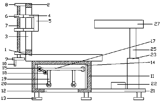
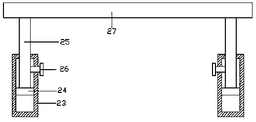
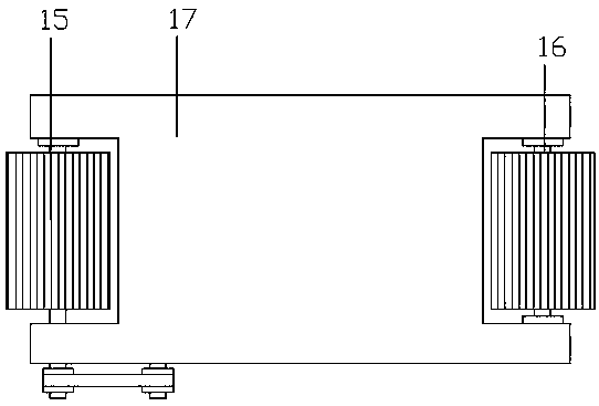
[0022] refer to Figure 1~3 , in an embodiment of the present invention, a special chair for peritoneal dialysis of medical equipment, including a seat board 1, a backing board 2 is fixedly arranged on the left end of the upper side of the seat board 1, an opening 3 is provided in the middle of the backing board 2, and the bottom board 1. A connecting seat 11 is welded on the lower side, and the bottom of the connecting seat 11 is provided with a connecting port 12. The outer end of the lower side of the connecting port 12 is welded with a supporting leg 13. The left and right side walls of the connecting seat 11 are welded with teeth Bar 14, the inside of the rack 14 is meshed with a gear 15, the gear 15 is connected with the connecting plate 17 through the connecting shaft 16, the left end of the lower side of the connecting plate 17 is equipped with a motor 18, and the motor 18 is connected with the The shaft 16 is connected, and the four corners of the lower side of the co...

Embodiment 2

[0025] The difference from Embodiment 1 is: fixed blocks 8 are fixedly installed at the upper and lower ends of the left side of the backing plate 2, and a screw rod 7 is installed on the fixed block 8, and a connecting block 6 is arranged on the screw rod 7, so that The left side of the connecting block 6 is connected with a connecting rod 4, the right side of the connecting rod 4 is provided with a back massager 5, the lower side of the screw rod 7 is provided with a rotating disc 9, and the lower left end of the rotating disc 9 is provided with a handle 10. By manually rotating the handle 10, the screw rod 7 can be driven to rotate, and the back massager 5 can be driven to adjust up and down, so that the back of the person can be massaged.


PUM


Abstract

The invention relates to the field of dialysis equipment, in particular to a chair special for peritoneal dialysis of medical equipment. The chair comprises a seat board, a backup plate is fixedly disposed at the left end on the upper side of the seat board, the middle part of the backup plate is equipped with an opening, a connecting seat is welded under the seat board, racks are welded on the left and right side walls inside the connecting seat, the insides of the racks are engaged with gears, the gears are connected to a connecting plate through connecting shafts, a motor is installed at aleft end under the connecting plate, the motor is connected to the connecting shaft through a belt, support legs are welded to four corners under the connecting plate, rollers are welded under the support legs, a fixed plate is welded to the lower end on the right side of the connecting seat, a foot massager is disposed at the right end on the fixed plate, connecting pipes are disposed at the front end and back end on the right side of the foot massager, the connecting pipes are internally equipped with connecting blocks, telescopic rods are disposed on the connecting blocks, and an operatingconsole is fixedly installed on the telescopic rods. The chair provided by the invention can effectively facilitate the movement and fixation of the equipment, thus facilitating use of the equipment.

Description

technical field [0001] The invention relates to the field of dialysis equipment, in particular to a special chair for peritoneal dialysis of medical equipment. Background technique [0002] Dialysis is the clinical meaning that some waste products in the blood are removed through a semi-permeable membrane. Hemodialysis is one of the safer, easier and widely used methods of blood purification. Dialysis is the movement of solutes from a solution of high concentration to a solution of low concentration through a semipermeable membrane. Hemodialysis includes the movement of solutes and water, that is, the blood and dialysate exchange substances in the dialyzer (artificial kidney) through semi-permeable membrane contact and concentration gradients, so that metabolic waste and excess electrolytes in the blood are transferred to the dialysate. Move, the calcium ions and bases in the dialysate move to the blood. [0003] The currently published Chinese patent authorization announ...

Claims


Application Information

Patent Timeline
IPC IPC(8): A61G15/00A61G15/10A61M1/28A61H7/00A61H39/04
CPCA61G15/00A61G15/10A61G2210/20A61H7/002A61H39/04A61H2205/081A61H2205/12A61H2205/125A61M1/28
Inventor 肖婷婷
Owner 成都市第五人民医院
Features
  • R&D
  • Intellectual Property
  • Life Sciences
  • Materials
  • Tech Scout
  • Unparalleled Data Quality
  • Higher Quality Content
  • 60% Fewer Hallucinations
Learn More