
Efficient drilling equipment for building construction

A construction and high-efficiency technology, applied in metal processing equipment, drilling/drilling equipment, manufacturing tools, etc., can solve the problems of low equipment work efficiency, inconvenient drilling equipment, inconvenient debris disposal, etc., to achieve convenient collection and Storage, convenient punching, and the effect of improving work efficiency

Inactive Publication Date: 2019-03-26
广西东创智能科技有限公司
View PDF0 Cites 8 Cited by
  • Summary
  • Abstract
  • Description
  • Claims
  • Application Information

AI Technical Summary

Problems solved by technology

[0004] In the process of building construction, it is often necessary to drill holes with multiple equipment, which can facilitate the installation of the equipment and the bolted connection. However, the current drilling equipment is generally simple in structure, so that the working efficiency of the equipment during the drilling process is low, and the equipment clamps the drilling hole. The equipment is very inconvenient, which is inconvenient for people to use. In addition, a lot of debris will be generated during the drilling process, which will cause great inconvenience in the disposal of debris around the drilling device.

Method used

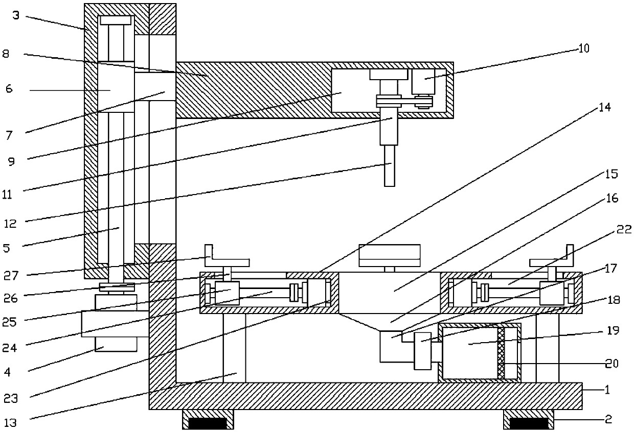

Image

  • Efficient drilling equipment for building construction
  • Efficient drilling equipment for building construction
  • Efficient drilling equipment for building construction

Examples


Embodiment Construction

[0019] It should be noted that, in the case of no conflict, the embodiments of the present invention and the features in the embodiments can be combined with each other.

[0020] In describing the present invention, it should be understood that the terms "center", "longitudinal", "transverse", "upper", "lower", "front", "rear", "left", "right", " The orientations or positional relationships indicated by "vertical", "horizontal", "top", "bottom", "inner" and "outer" are based on the orientations or positional relationships shown in the drawings, and are only for the convenience of describing the present invention and Simplified descriptions, rather than indicating or implying that the device or element referred to must have a particular orientation, be constructed and operate in a particular orientation, and thus should not be construed as limiting the invention. In addition, the terms "first", "second", etc. are used for descriptive purposes only, and should not be understood ...


PUM


Abstract

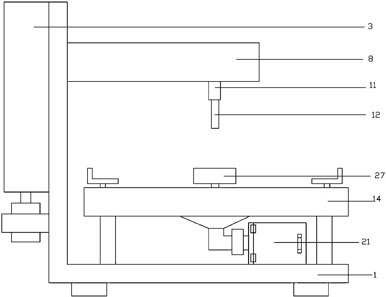
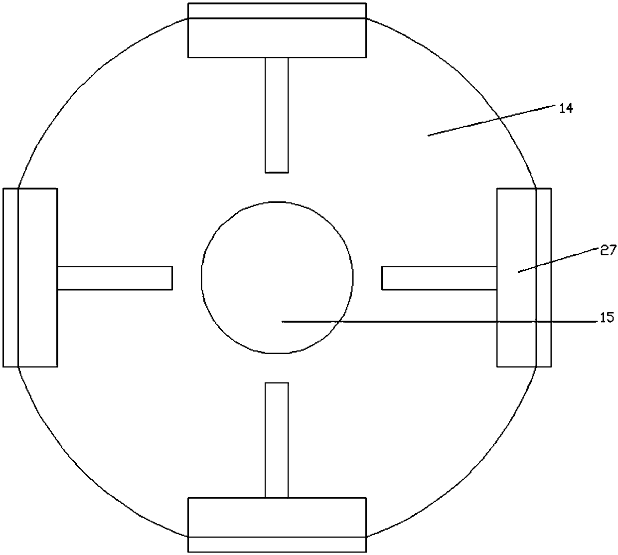
The invention discloses efficient drilling equipment for building construction. The efficient drilling equipment for building construction comprises an L-shaped support plate, a sliding groove is formed in the left side of the L-shaped support plate, a first motor is arranged on the lower side of the sliding groove, a first screw rod is arranged on the upper side of the first motor, a first sliding block is arranged on the first screw rod, a connecting rod is arranged on the right side of the first sliding block, a supporting plate is arranged on the right side of the connecting rod, a connecting cavity is formed inside the support plate, a second motor is arranged at the right end of the connecting cavity, a bit connecting seat is arranged on the left side of the second motor, supportinglegs are arranged at four corners of the upper side of the L-shaped support plate, a connecting exhaust pipe is arrange on the upper sides of the supporting legs, an impurity storage box is arranged on the right side of the exhaust pipe, a sliding groove is formed in the periphery of the outer side of an opening, a third motor is arranged at the inner end inside the sliding groove, a second screwrod is arranged on the outer side of the third motor, a second sliding block is arranged on the second screw rod, a supporting rod is arranged on the upper side of the second sliding block, and an L-shaped clamping plate is arranged on the upper side of the supporting rod. According to the efficient drilling equipment for building construction, continuous drilling of the equipment is effectively facilitated, impurity storage of drilling is convenient, and thus using of people is convenient.

Description

technical field [0001] The invention relates to the field of building construction, in particular to a high-efficiency hole turning equipment for building construction. Background technique [0002] Building construction is a production process that people use various building materials and mechanical equipment to build various building products in a certain space and time according to a specific design blueprint. It includes the entire production process from construction preparation, groundbreaking to project completion acceptance. In this process, construction preparation, construction organization design and management, earthwork engineering, blasting engineering, foundation engineering, steel reinforcement engineering, formwork engineering, scaffolding engineering, concrete engineering, prestressed concrete engineering, masonry engineering, steel structure engineering, and timber structure will be carried out. Engineering, structural installation engineering, etc. [...

Claims


Application Information

Patent Timeline
Patent Type & Authority Applications(China)
IPC IPC(8): B23Q1/26B23Q3/06B23Q11/00B23B39/00
CPCB23Q1/26B23B39/00B23Q3/06B23Q11/0046
Inventor 梁毅颉汪治兴陆日琪
Owner 广西东创智能科技有限公司
Learn More