
A conveying engraving mechanism and its working method for electronic accessories processing line

An assembly line and engraving machine technology, which is applied in the direction of engraving, processing models, painting tools, etc., can solve the problems of easy vibration or movement of electronic accessories, poor work diversity, poor stability of electronic accessories, etc., so that electronic accessories can be transported on the mechanism Smooth movement, convenient installation or disassembly, and high space utilization

Active Publication Date: 2020-09-29
徐州彤宇自动化科技有限公司
View PDF6 Cites 0 Cited by
  • Summary
  • Abstract
  • Description
  • Claims
  • Application Information

AI Technical Summary

Problems solved by technology

[0004] The purpose of the present invention is to solve the problem that the existing conveying mechanism used for the processing line of electronic accessories cannot carry out engraving processing on the electronic accessories while conveying the electronic accessories. The stability of electronic accessories is poor when being transported. Electronic accessories are easy to shake or move when being transported, resulting in damage, and the staff cannot adjust the conveying angle of the conveying mechanism to the electronic accessories for different sizes and types of electronic accessories. The conveying mechanism The adjustable flexibility is poor, and the conveying mechanism is inconvenient to move and adjust the working position, so a conveying engraving mechanism for electronic accessories processing line is proposed

Method used


Image

  • A conveying engraving mechanism and its working method for electronic accessories processing line
  • A conveying engraving mechanism and its working method for electronic accessories processing line
  • A conveying engraving mechanism and its working method for electronic accessories processing line

Examples


Embodiment Construction

[0045] The technical solutions of the present invention will be clearly and completely described below in conjunction with the embodiments. Apparently, the described embodiments are only some of the embodiments of the present invention, not all of them. Based on the embodiments of the present invention, all other embodiments obtained by persons of ordinary skill in the art without creative efforts fall within the protection scope of the present invention.

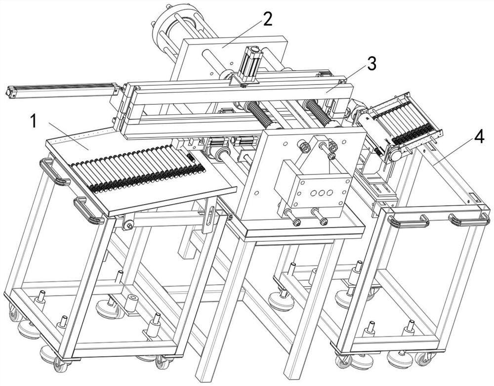
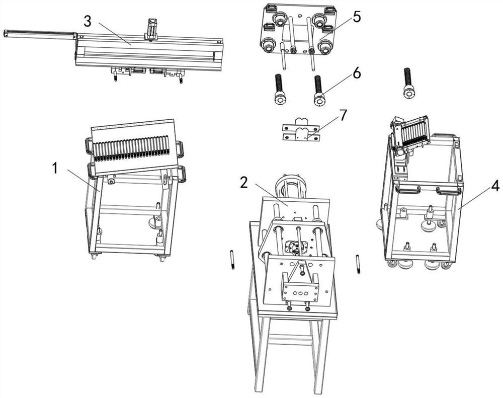
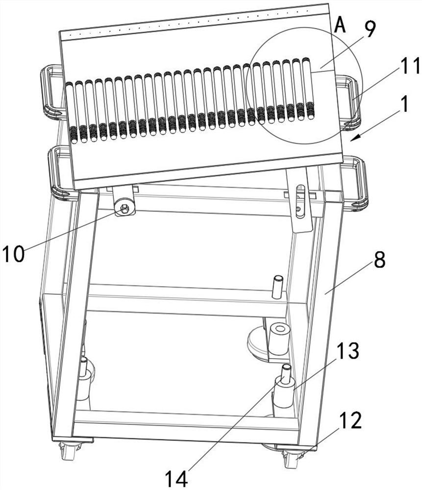
[0046] see Figure 1-12 As shown, a conveying and engraving mechanism used in an electronic accessories processing line includes a front feeding table 1, an inner feeding table 2, an engraving plate 3 and a rear feeding table 4, and the inner feeding table 2 is set on the front feeding table 1 and the rear feeding table Between 4, the front delivery platform 1 and the rear delivery platform 4 are respectively connected to both ends of the inner delivery platform 2 by bolts, and the upper end of the inner delivery platform 2...


PUM


Abstract

The invention discloses a conveying and carving mechanism for an electronic accessory processing assembly line. The conveying and carving mechanism for the electronic accessory processing assembly line comprises a front transmission table, an inner transmission table, a carving disc and a back transmission table, wherein the inner transmission table is arranged between the front and the back transmission tables, the front and back transmission tables are separately connected with both ends of the inner transmission table through bolts, and the carving disc is arranged at the upper end of the inner transmission table. The conveying and carving mechanism for the electronic accessory processing assembly line has the beneficial effects that a plurality of tooth rings drive rotating sleeves torotate through a plurality of rolling teeth arranged on the side walls of the tooth rings at equal radians to drive electronic accessories to move and be transported, and the electronic accessories being transported and moves more smoothly and reliably on the mechanism are ensured; and a third motor on the back transmission table drives a tilting and conveying disk to reverse and adjust the angleof the electronic accessories, so that the mechanism is ensured to be more accurate and suitable during transporting the electronic accessories with different sizes to a next processing point position, and the flexibility of the use is ensured. The mechanism has convenient operation, high automation degree of working, good social and economic benefits, and is suitable for popularization and use.

Description

technical field [0001] The invention relates to an engraving mechanism, in particular to a conveying and engraving mechanism used in an electronic accessory processing line and a working method thereof, belonging to the technical field of conveying and engraving mechanisms. Background technique [0002] Electronic accessories often require engraving machines to engrave shape or model information on the outer wall of the accessories in the processing line. In the processing line, the electronic accessories are first transported to the engraving machine through the conveying mechanism, and then the engraving machine engraves the accessories. [0003] There are still many deficiencies in the existing conveying mechanism for the electronic accessories processing line when it is working. The existing conveying mechanism for the electronic accessories processing line cannot carry out engraving processing on the electronic accessories while conveying the electronic accessories , th...

Claims


Application Information

Patent Timeline
Patent Type & Authority Patents(China)
IPC IPC(8): B44B1/06B44B1/00B44B3/06B44B3/00
CPCB44B1/00B44B1/06B44B3/005B44B3/06B44B2700/02B44B2700/04B44B2700/12
Inventor 吴有军
Owner 徐州彤宇自动化科技有限公司
Learn More