Curvilinear circular polarizer

A circular polarizer and curved technology, applied in the field of communication, can solve the problems of complex production, high processing cost, and many layers of printed boards, and achieve low profile, high-purity circular polarization, and high circular polarization purity. Effect

Active Publication Date: 2019-03-26
SICHUAN JIUZHOU ELECTRIC GROUP
View PDF6 Cites 1 Cited by
  • Summary
  • Abstract
  • Description
  • Claims
  • Application Information

AI Technical Summary

Problems solved by technology

[0005] In view of the above analysis, the embodiment of the present invention aims to provide a curved circular polarizer to solve the problems of the prior art with many layers of printed boards, complex fabrication, and high processing costs

Method used


Image

  • Curvilinear circular polarizer
  • Curvilinear circular polarizer
  • Curvilinear circular polarizer

Examples


Embodiment 1

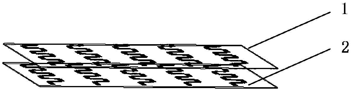
[0045] A specific embodiment of the present invention discloses a curved circular polarizer, including an upper curved grid layer 1 and a lower curved grid layer 2 arranged in parallel from top to bottom, as figure 1 As shown, the two curved gate layers are aligned from top to bottom.

[0046] The linearly polarized wave passes through the lower curved grid layer 2 and the upper curved grid layer 1 sequentially from bottom to top.

[0047] The lower curved grid layer 2 is used to receive a linearly polarized wave whose electric field vector forms an angle of 45° with the plane of the lower curved grid layer 2, and generate a linearly polarized electric field vector 1 around it.

[0048] The upper curved grid layer 1 is used to receive the linearly polarized wave, generate a linearly polarized electric field vector 2 with a 90° phase difference with the linearly polarized electric field vector 1, and generate a left-handed wave above the upper curved grid layer 1. Or right-han...

Embodiment 2

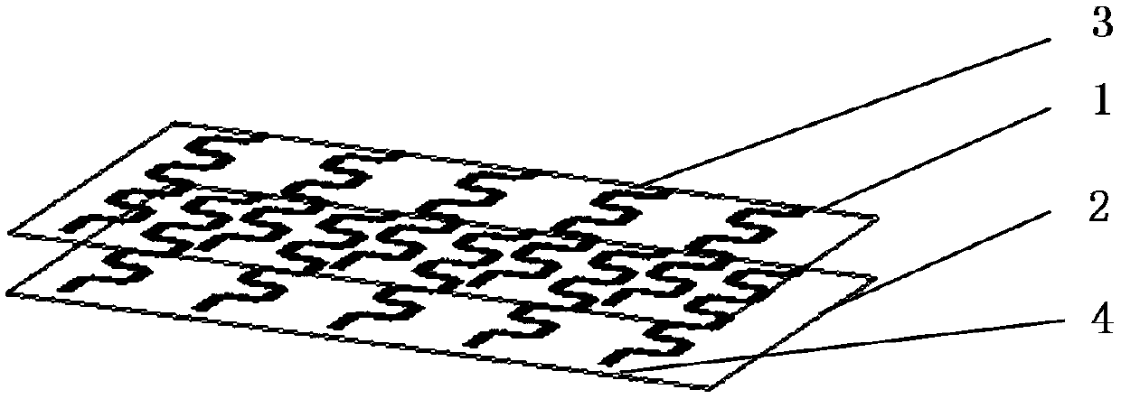
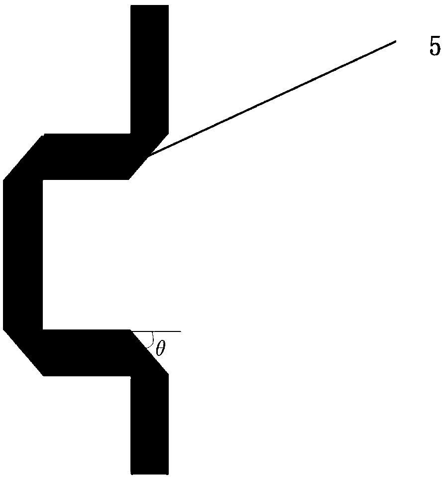
[0052] Optimizing on the basis of Example 1, such as figure 2 As shown, the upper curved grid layer 1 includes M groups of curved metal grids 3 arranged periodically in the direction of the grids, and N corner-cutting basic units in each group are arranged periodically. The corner-cutting basic unit adopts a rectangular wave unit structure with corner cutting; the M≥2, N≥2. The corner-cut basic unit can reduce the standing wave, reduce the S11 value, and reduce the transmission loss. Therefore, the curved metal grid constructed by the corner-cutting basic unit can blunt the sharp edges, reduce the VSWR, reduce the S11 value, and reduce the transmission loss.

[0053] Preferably, the above periodic arrangement may be a horizontal periodic arrangement.

[0054] Preferably, the structure, size and parameters of the lower curved gate layer 2 are the same as those of the upper curved gate layer 1 . That is, both have the same set of M curved metal grids 4, such as figure 2 sh...


PUM


Abstract

The invention relates to a curvilinear circular polarizer and belongs to the technical field of communication to solve the problem in the prior art that a printed board has a large number of layers, and is complicated to manufacture and high in processing cost. The curvilinear circular polarizer includes an upper curvilinear gate layer and a lower curvilinear gate layer arranged in parallel from top to bottom. The lower curvilinear gate layer is used for receiving a linearly polarized wave where an electric field vector and the lower curvilinear gate layer plane have an intersection angle of 45 degrees, and generating a linearly polarized electric field vector 1 around the linearly polarized wave. The linearly polarized wave passes through the lower curvilinear gate layer and the upper curvilinear gate layer from bottom to top. The upper curvilinear gate layer is used for receiving the linearly polarized wave, generating a linearly polarized electric field vector 2 having a phase difference of 90 degrees with the linearly polarized electric field vector 1, and generating a left-handed or right-handed circularly polarized wave over the upper curvilinear gate layer. The curvilinear circular polarizer has a wide band, low profile, low loss, low cost, high circular polarization fineness, simple structure, light weight, less accessory structure, and is easy to process and assemble.

Description

technical field [0001] The invention relates to the technical field of communications, in particular to a curved circular polarizer. Background technique [0002] Circular polarizers have important application value in the fields of radar detection and communication. Putting them in front of the radiation port of linearly polarized antennas can convert linearly polarized waves into circularly polarized waves. The axial ratio of a circularly polarized antenna is an important index to measure the purity of circular polarization. The smaller the axial ratio of a circularly polarized antenna, the higher the circular polarization purity of the antenna. The voltage standing wave ratio is an important index to measure the matching degree between the antenna and the circular polarizer. The larger the standing wave ratio is, the worse the matching is. If the standing wave ratio is less than 1.5, the antenna matching is very good and the transmission efficiency is high. [0003] S11 ...

Claims


Application Information

Patent Timeline
Patent Type & Authority Applications(China)
IPC IPC(8): H01Q15/24
CPCH01Q15/244
Inventor 黄亮阳松韩垒郑万清党涛
Owner SICHUAN JIUZHOU ELECTRIC GROUP
Why Eureka
Try Eureka