Z-reference plane detection and setting method for vertical miller

A datum plane and vertical milling machine technology, applied in the direction of measuring/indicating equipment, metal processing equipment, metal processing machinery parts, etc., can solve the problems of poor reliability, slow speed to the initial origin, etc., to reduce datum error and suppress datum The effect of correcting errors and improving the efficiency of correcting

Active Publication Date: 2019-03-29
CHENGDU AIRCRAFT INDUSTRY GROUP
View PDF5 Cites 10 Cited by
  • Summary
  • Abstract
  • Description
  • Claims
  • Application Information

AI Technical Summary

Problems solved by technology

[0007] The purpose of the present invention is to provide a method for aligning the Z-direction datum plane with the probe suitable for vertical milling machines, which solves the problem of slow speed and poor reliability in the initial origin of the Z-direction of the manual setting of the processing coordinate system in the process of numerical control machining.

Method used


Image

  • Z-reference plane detection and setting method for vertical miller
  • Z-reference plane detection and setting method for vertical miller
  • Z-reference plane detection and setting method for vertical miller

Examples


Embodiment 1

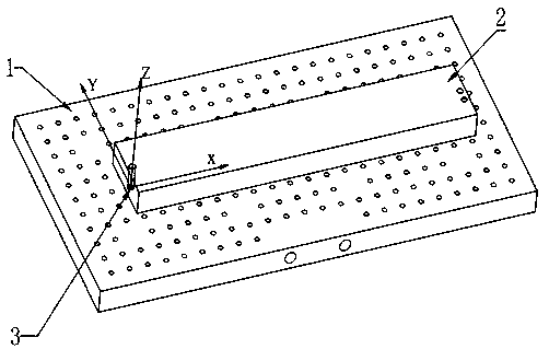
[0050] The present invention is realized through the following technical solutions, as Figure 1-Figure 6 As shown, the Z-direction datum plane detection and setting method of the vertical milling machine uses the probe to align the datum processing plane and calibrate. Before measuring, determine the contour of the plane according to the size and position of the blank 2 of the part on the tooling, and take the contour of the positioning plane as the boundary , according to the position of the positioning surface of the part, select a number of sampling points as the sampling position, and within the tolerance range, take the average value of the Z values ​​of the sampling points as the position of the Z-direction reference plane.

[0051] Further, in order to better realize the present invention, specifically include the following steps:

[0052] Step B: probe calibration;

[0053] Step C: According to the placement position of the part blank 2, determine the detection area ...

Embodiment 2

[0076] This embodiment is further optimized on the basis of the above embodiments, such as figure 1 , figure 2 As shown, a Z-direction reference plane detection and setting method suitable for vertical milling machines is characterized in that it adopts an automatic measurement method using probe detection and a standard measurement program for nested CNC systems, and the probe used has position detection perception function, and can feed back the measurement results to the control system; the automatic measurement method is composed of a tool cleaning method, a probe length calibration method, a probe diameter calibration method, and a Z-direction plane probe measurement method;

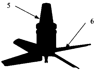
[0077] The tool cleaning method described above uses a special fan for cleaning. The structure of the fan is similar to that of the cutting tool. The working part is a fan blade, which is connected to the main shaft of the machine tool through the tool handle. When cleaning, the main shaft rotates ...

Embodiment 3

[0087] The preferred embodiment of the Z-direction reference plane detection and setting method of the vertical milling machine in the present invention is as figure 1 Shown is a part to be processed, using positioning tool 1 for clamping and positioning, the positioning method of the part blank 2 is process hole and reference plane positioning, the origin 3 of the machining coordinate system is located at the left process hole, and the Z-direction reference plane is on the positioning tool 1 surface.

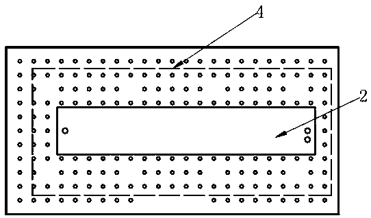
[0088] Use the probe to align the reference processing plane. Firstly, it is necessary to clean the upper surface of the positioning tool 1, draw a line according to the size of the part blank 2 to determine the contour 4 of the cleaning area, and remove the part blank 2.

[0089] Use clean fan structures such as image 3 As shown, the fan is composed of a fan body 5 and fan blades 6. The fan is connected to the main shaft of the machine tool. The rotation of the main shaft dr...


PUM


Abstract

The invention discloses a Z-reference plane detection and setting method for a vertical miller. The Z-reference plane detection and setting method comprises the following steps of using a probe to perform alignment of a reference processed plane and calibration, determining a positioning plane contour on a tool according to the size and the position of a part blank before measurement, selecting aplurality of sampling points as sampling positions according to a part positioning plane position by taking the positioning plane contour as a boundary, and taking an average value of Z values of thesampling points as the position of a Z-reference plane. The Z-reference plane detection and setting method provided by the invention effectively solves the problems of slow speed, poor reliability andlow accuracy of manually setting Z initial origins of a processing coordinate system in the numerical control machining process.

Description

technical field [0001] The invention relates to the technical field of numerical control machining, in particular to a method for detecting and setting a Z-direction reference plane of a vertical milling machine. Background technique [0002] Machining technology generally follows the "positioning-processing" operation mode. According to this mode, how to follow the design and process [0003] It is required to realize the precise positioning of the workpiece to be processed and establish the corresponding processing coordinate system has become the most important work content in the processing process. When establishing the processing coordinate system, the alignment and setting of the Z-direction reference plane are the first steps. At this stage, for [0004] For vertical machine tools, the manual alignment method is the most commonly used method. During alignment, the operator uses a standard tool setting block to manually set the tool on the machine tool to find the po...

Claims


Application Information

Patent Timeline
Patent Type & Authority Applications(China)
IPC IPC(8): B23Q17/22B23Q17/00B23Q11/00
CPCB23Q11/00B23Q17/00B23Q17/22
Inventor 黄方林杨京京高锦焜
Owner CHENGDU AIRCRAFT INDUSTRY GROUP
Why Eureka
Try Eureka