
Roof rainwater collecting and utilizing system

A rainwater and collecting pipe technology, applied in air conditioning systems, roof insulation materials, applications, etc., can solve the problems of single and traditional utilization methods, and achieve the effect of large temperature adjustment range, large contact area, and reduced blockage.

Pending Publication Date: 2019-03-29
XINYANG NORMAL UNIVERSITY
View PDF1 Cites 4 Cited by
  • Summary
  • Abstract
  • Description
  • Claims
  • Application Information

AI Technical Summary

Problems solved by technology

Therefore, making full use of rainwater is a good way to make full use of water resources, and it is more common to use the roof collection device to collect rainwater. The roof collection device is divided into two parts, namely the rainwater receiving area on the roof and the water collection on the lower floor The device, the rainwater receiving area and the water collection device are connected through pipelines; at present, this method can only simply treat the collected rainwater, and is mainly used for watering flowers and plants. The rainwater collection and storage system for green land includes a rainwater receiving area on the roof for collecting rainwater and a water collecting device installed on the ground floor. A rainwater delivery riser is connected between the rainwater receiving area and the water collection device. The rainwater delivery stand The pipe is located outside the wall; the water collection device includes a reservoir. Although the rainwater in the reservoir can be connected to the sprinkler irrigation pipeline on the ground through the pump and the control valve, it is used for ground sprinkler irrigation, but this utilization method is relatively traditional and single.

Method used


Image

  • Roof rainwater collecting and utilizing system
  • Roof rainwater collecting and utilizing system
  • Roof rainwater collecting and utilizing system

Examples


Embodiment Construction

[0026] Embodiments of the present invention will be further described below in conjunction with the accompanying drawings.

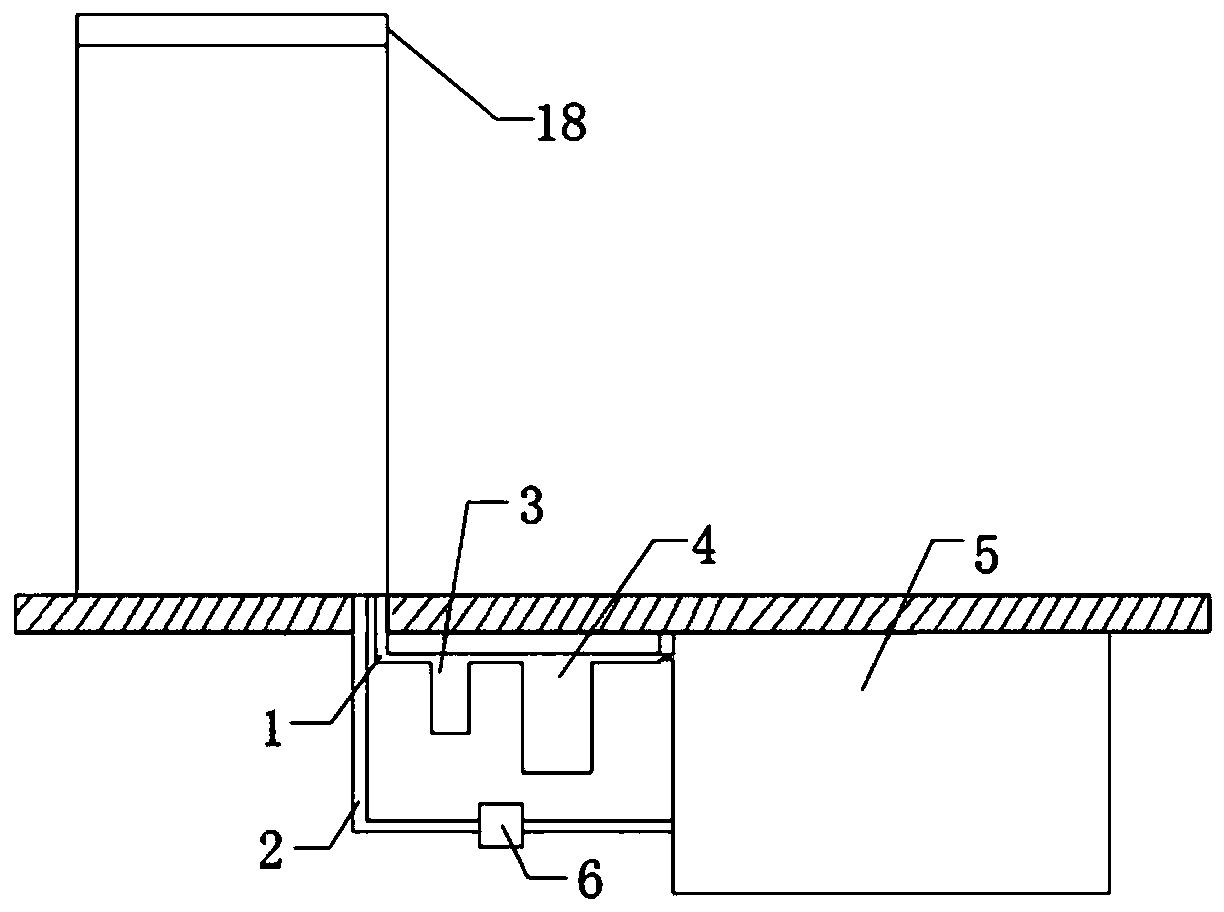
[0027] Embodiment 1 of the roof rainwater collection and utilization system of the present invention, as Figure 1 to Figure 4 As shown, the roof rainwater collection and utilization system includes a rainwater receiving area 7 and a water collecting device 5. The rainwater receiving area 7 is located on the roof 18 of the building, and is connected to the water collecting device 5 below the ground through the header pipe 1.

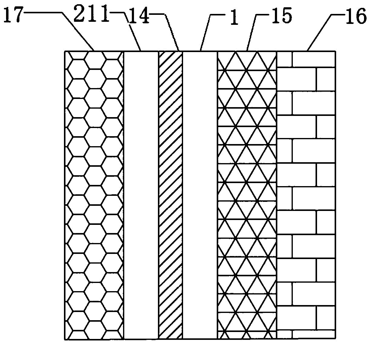
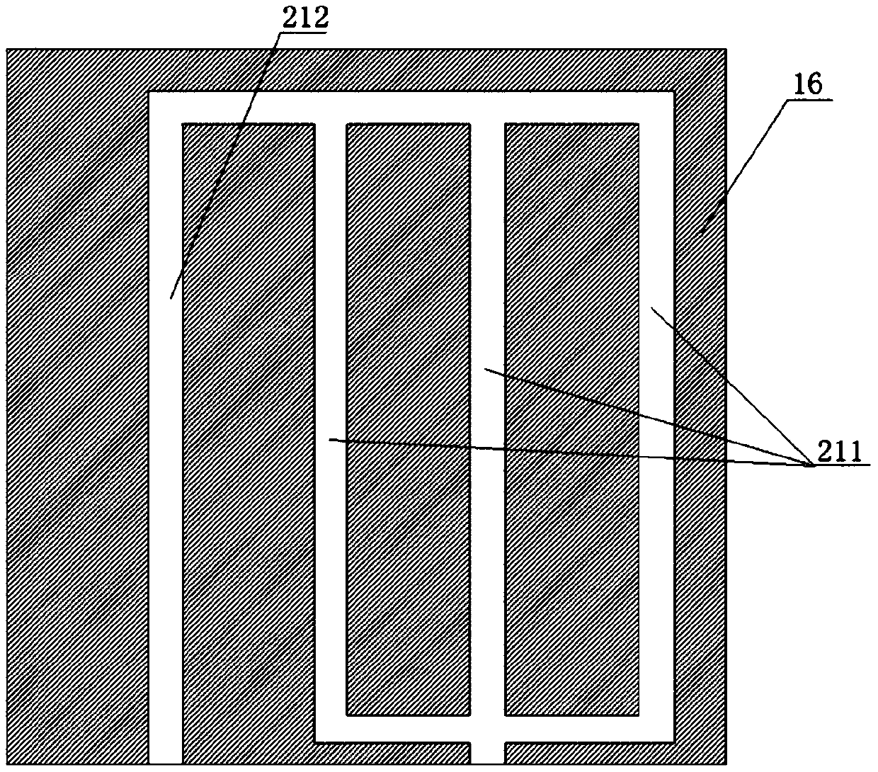
[0028] The roof rainwater collection and utilization system also includes a water exchange pipe 2 that communicates with the water collection device 5 and forms a water cycle with the water collection device 5, such as figure 2 As shown, both the water exchange pipe 2 and the header 1 are arranged in the wall 16 of the building, the water exchange pipe 2 and the header 1 are arranged side by side along the thickness direction of t...


PUM


Abstract

The invention provides a roof rainwater collecting and utilizing system. The system comprises a rainwater receiving area positioned on a roof of a building, wherein the rainwater receiving area is connected to a water collecting device under the ground through a flow collecting pipe; the roof rainwater collecting and utilizing system also comprises a heat exchange water pipe arranged in a wall body of the building, the heat exchange water pipe is communicated with the water collecting device for circulation through a water pump. Through the work of the water pump, rainwater of the water collecting device at the low position is conveyed to a high position in the wall body of the building and pushed to circularly flow in the heat exchange water pipe, so that the rainwater in the heat exchange water pipe exchanges heat with the building, the rainwater is continuously circulated between the heat exchange water pipe and the water collecting device in order to adjust the indoor temperature,and diversified utilization of the rainwater is achieved.

Description

technical field [0001] The invention specifically relates to a roof rainwater storage and utilization system. Background technique [0002] In recent years, with the acceleration of urbanization in our country, the proportion of urban impervious areas has been increasing, the surface runoff has increased, and the pollution of rainwater runoff has become more and more serious with urbanization and industrialization. Therefore, making full use of rainwater is a good way to make full use of water resources, and it is more common to use the roof collection device to collect rainwater. The roof collection device is divided into two parts, namely the rainwater receiving area on the roof and the water collection on the lower floor The device, the rainwater receiving area and the water collection device are connected through pipelines; at present, this method can only simply treat the collected rainwater, and is mainly used for watering flowers and plants. The rainwater collection ...

Claims


Application Information

Patent Timeline
IPC IPC(8): E03B3/02E04D13/16F24F5/00
CPCF24F5/0003E03B3/02E04D13/1687Y02A20/108
Inventor 翟慧敏李子豪张迁谢文全
Owner XINYANG NORMAL UNIVERSITY
Learn More