
Steel structure building cast-in-place concrete hollow floor system self-bearing hanging bracket formwork erecting technology

A technology for an empty floor and concrete, which is applied to the on-site preparation of building components, construction, building construction, etc., can solve problems such as hindering the immediate advancement of construction projects, heavy erection and demolition work, and long demolding cycle, etc., to eliminate The effect of heavy manual labor, reduction of labor costs for mold support, and convenient transportation

Inactive Publication Date: 2019-03-29
仇国辉
View PDF7 Cites 3 Cited by
  • Summary
  • Abstract
  • Description
  • Claims
  • Application Information

AI Technical Summary

Problems solved by technology

But its disadvantage is that it needs to consume a lot of turnover steel frame pipes and a lot of formwork labor, especially the erection of full house formwork. Its erection and dismantling work is heavy, and the form removal cycle is long, which seriously hinders the construction of other construction processes. Immediate advancement, this is an important defect of the traditional formwork technology, the current floor construction technology of concrete frame structure and load-bearing wall structure building is still difficult to break through the traditional formwork technology

Method used


Image

  • Steel structure building cast-in-place concrete hollow floor system self-bearing hanging bracket formwork erecting technology
  • Steel structure building cast-in-place concrete hollow floor system self-bearing hanging bracket formwork erecting technology
  • Steel structure building cast-in-place concrete hollow floor system self-bearing hanging bracket formwork erecting technology

Examples


Embodiment Construction

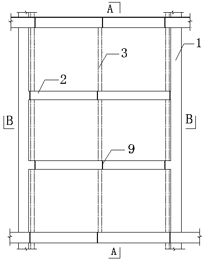
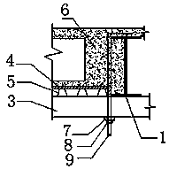
[0032] Such as figure 1 , figure 2 , image 3 , Figure 4 , Figure 5 , Image 6 As shown, the construction process of the present invention is as follows: welding supporting form force suspension rod→installing supporting form steel beam base→fixing supporting form steel beam→laying corrugated steel plate→full paving wood template→binding steel bar→pouring concrete.

[0033] Construction requirements of the invention:

[0034] 1. Formwork force suspension rod 9 adopts M14 screw rod, the length is determined according to the thickness of the floor, generally 550-600 long, the top is bent at 90°, and the end hook length is not less than 100, and it is firmly welded and fixed on the building floor. The upper part of the steel beam.

[0035] 2. Forced support top support

[0036] ①It is used for individual unable to set the position of the force supporting rod.

[0037] ②It is used to strengthen and support the bottom of H100 steel beam in the middle of the room, generally no less than ...


PUM


Abstract

The invention relates to a steel structure building cast-in-place concrete hollow floor system self-bearing hanging bracket formwork erecting technology. The technology is characterized in that an all-around formwork erecting stress mode of traditional concrete cast-in-place is canceled, and the structure steel beam stress mode of a concrete floor to be poured is adopted for formwork erecting. Thetechnology has the advantages that the purpose of rust removal of a steel structure is effectively achieved; the floor cast-in-place concrete construction formwork erecting turnover material consumption and transporting amount are reduced; the formwork erecting manual cost is greatly lowered, and the labor intensity is lowered; the project quality is ensured; alternate construction of other projects is facilitated, and the construction period is greatly shortened.

Description

Technical field [0001] The invention relates to the technical field of building construction, in particular to a self-supporting hanger mold-supporting process for cast-in-situ concrete hollow floors of steel structures. Background technique [0002] Ordinary steel structure buildings are developing vigorously and are widely used, especially in multi-storey buildings. The application advantages are more obvious. It has a firm structure, convenient construction, high degree of industrial production and assembly, and rapid construction progress. The amount of steel used within a certain height range is also moderate, and will not be significantly greater than that of reinforced concrete structures. [0003] However, as the main structural part of the building, the construction technology reform of the floor construction has a positive and important significance. The existing formwork technology of the traditional concrete frame (shear) structure and the mixed structure floor construc...

Claims


Application Information

Patent Timeline
Patent Type & Authority Applications(China)
IPC IPC(8): E04B1/35E04G11/48
CPCE04B1/35E04G11/48
Inventor 仇国辉
Owner 仇国辉
Learn More