Back-clamp-type facing wallboard locking device

A locking device, back clip technology, applied in covering/lining, architecture, building structure, etc., can solve the problems of excessive swing of cutting blades, inability to physically connect, and inability to actively control, to increase the force area, meet the pull-out resistance, improve the effect of friction

Pending Publication Date: 2019-03-29
杨义生 +1
View PDF0 Cites 1 Cited by
  • Summary
  • Abstract
  • Description
  • Claims
  • Application Information

AI Technical Summary

Problems solved by technology

From the working method of the above-mentioned fastener, it can be concluded that the pull-out resistance of the fastener is proportional to the pull-out performance of the decorative material and the thickness of the fastened decorative material; under a certain thickness of the decorative material, the fastener obtains a tensile strength Pull-out force can only depend on the pull-out resistance of decorative materials, especially natural decorative materials, whose structure is unstable, resulting in extremely uncontrollable pull-out force of fasteners
The pull-out resistance of fasteners is extremely uncontrollable, and safety cannot be actively controlled
[0005] 2. It cannot be purely physical connection
The chemical properties of glue determine that its connection strength and connection life cannot reach the ability of physical connection
The purely physical connection cannot be achieved, which means that the connection force and service life of the fastener are greatly affected by the quality of the glue
[0006] 3. Thin decorative materials cannot be dry hung
[0007] 4. It is inconvenient to process the connection points of decorative materials, which will easily affect the strength and connection quality of decorative materials
Due to the limited thickness of the decorative material, the degree of freedom of the side groove is small, the cutting disc swing is too large or the depth is too deep, which will easily lead to a decrease in the structural strength of the decorative material, or even a defect, which will reduce the pull-out resistance of the decorative material and affect the use.
The quality of the back bolt hole directly determines the pull-out force of the back bolt; there are two reasons why the quality of the back bolt hole is uncontrollable: 1. The drill bit is easy to deform, and the drilled holes often change; 2. Due to the small hole, the drilled Pore ​​quality is difficult to detect
Therefore, in the structural design of the pass-through fasteners, there is a lack of consideration for the convenience of decorative materials processing, which will eventually affect the connection quality

Method used


Image

  • Back-clamp-type facing wallboard locking device
  • Back-clamp-type facing wallboard locking device
  • Back-clamp-type facing wallboard locking device

Examples


Embodiment 1

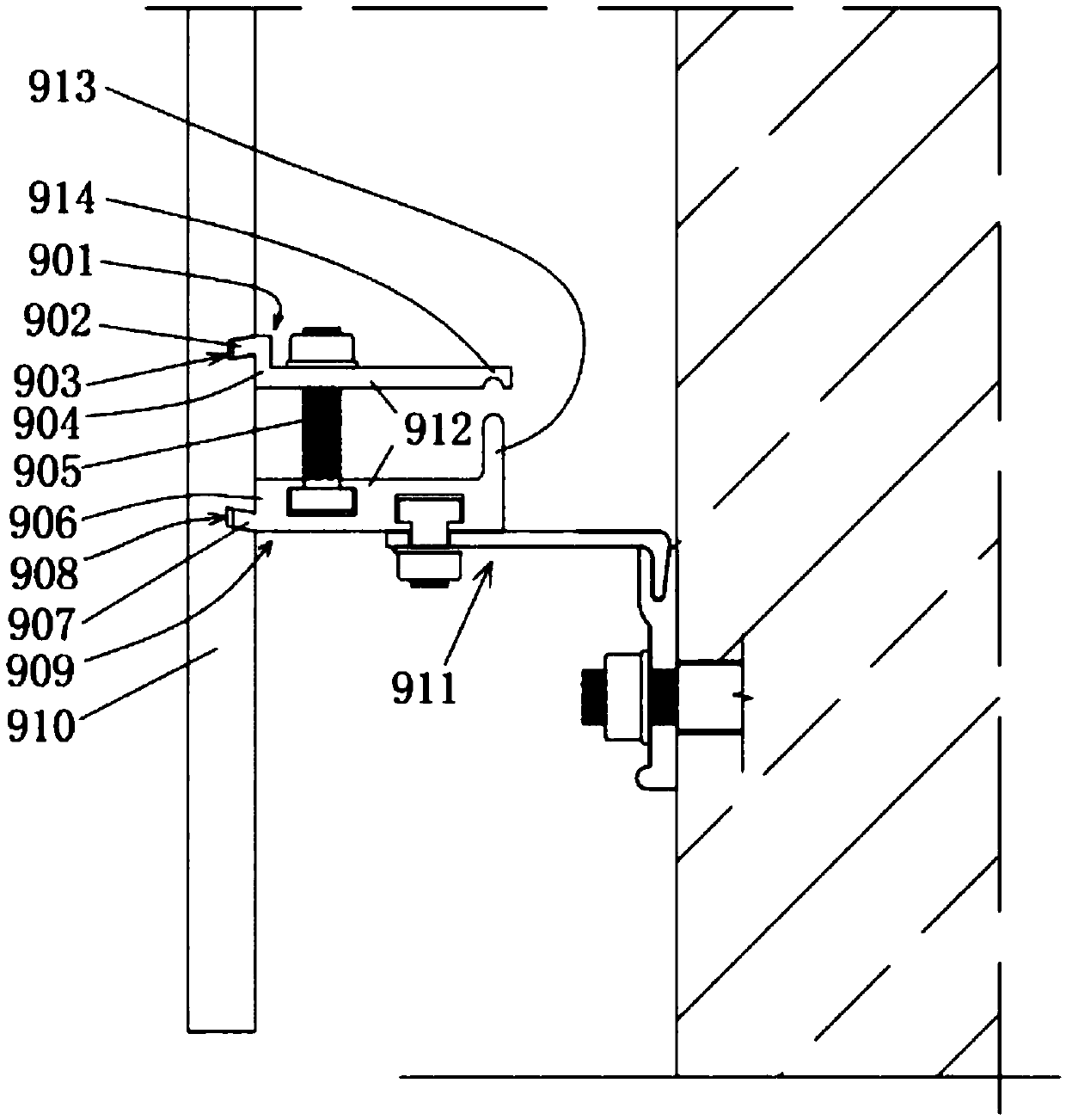
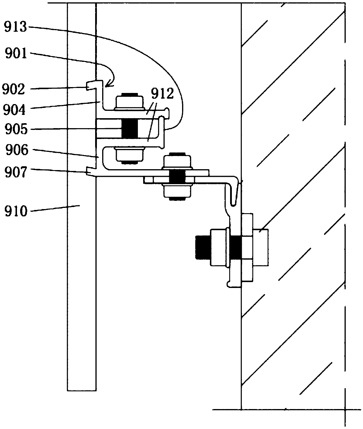
[0041] Embodiment 1, the back clip-type decorative wall panel locking device includes an upper clamping part 901 and a lower clamping part 909,

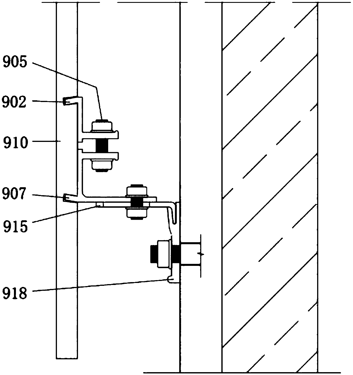
[0042] The outer end of the upper clamping member 901 is folded toward the side where the facing wallboard 910 is located to form an upper clip 902, and the upper clip is embedded in the upper groove 903 on the back of the facing wallboard;

[0043] The outer end of the lower clamping member 909 is folded toward the side where the facing wallboard is located to form a lower clip 907, and the lower clip 907 is embedded in the lower groove 908 on the back of the facing wallboard;

[0044] The upper clamping piece 901 and the lower clamping piece 909 are fixed by bolts 905 , and the upper clamping leaf 902 and the lower clamping leaf 907 cooperate to clamp the facing wallboard 910 .

[0045] A supporting member 913 extends from the rear of one of the upper clamping member 901 or the lower clamping member 909, and the supporting member a...

Embodiment 2

[0052] Embodiment 2. This embodiment is basically the same as Embodiment 1. The difference is that the lower part of the lower clamping member 909 is further extended to form a connecting plate, and the wall bracket assembly 911 is locked by bolts on the connecting plate. . In the upper folder of this embodiment, the inner end of the base plate extends toward the wall to form a bolt seat 912 . In the lower folder of this embodiment, the inner end of the base plate extends toward the wall to form a bolt seat 912 .

Embodiment 3

[0053] Embodiment 3. This embodiment is basically the same as Embodiment 2, the difference is that the relevant design of the support member 913 is cancelled.


PUM


Abstract

The invention belongs to the technical field of facing wallboard installing, and particularly discloses a back-clamp-type facing wallboard locking device. The back-clamp-type facing wallboard lockingdevice comprises an upper clamping piece and a lower clamping piece, the outer end of the upper clamping piece is turned towards one side of a facing wallboard or straightly extends to form an upper clamping sheet, and the upper clamping sheet is embedded into an upper groove in the back face of the facing wallboard; the outer end of the lower clamping piece is turned towards one side of the facing wallboard or straightly extends to form a lower clamping sheet, and the lower clamping sheet is embedded into a lower groove of the back face of the facing wallboard; the upper clamping piece and the lower clamping piece are fixed with a bolt through a structural supporting point, and the upper clamping sheet is matched with the lower clamping sheet to clamp the facing wallboard. The back-clam-type facing wallboard locking device adopts a back-clamp mode, short grooves are formed in the back face of a decorating material, and correspond to form two parallel faces or wedge-shaped, the clamping sheets enter the grooves, anti-drawing force is formed through friction force generated by clamping force of the clamping pieces, and the safety of the decorating material is guaranteed.

Description

technical field [0001] The invention belongs to the technical field of installation of decorative wall panels, in particular to a back-clip type decorative wall panel locking device. Background technique [0002] The invention is suitable for hanging and sticking engineering of facing materials on the surface of indoor and outdoor walls of buildings. Materials such as stone, thermal insulation composite board, magnetic board, wood and glass etc. Techniques are divided into two categories: 1. chemical means, 2. physical means. Chemical installation mainly uses construction glue or cement, pasting or grouting, etc. to install decorative materials on the wall. The water absorption rate of the wood and the pulp material are different, and the coefficients of thermal expansion and contraction are different. Especially under outdoor conditions, they will separate and fall off in a short time, posing serious safety problems. This installation technology is basically not used exc...

Claims


Application Information

Patent Timeline
Patent Type & Authority Applications(China)
IPC IPC(8): E04F13/24E04F13/22
CPCE04F13/0814E04F13/0819
Inventor 杨义生黄泓萍
Owner 杨义生
Why Eureka
Try Eureka