
Concrete filled steel tube arc frame for supporting architecture corridor

A technology of concrete filled steel tube and corridor, applied in the field of arch frame, can solve the problems of the overall strength and service life of the arch frame, lack of side support structure, inconvenient transportation and handling, etc., to extend service life and use safety, reduce installation The effect of labor intensity and simple structure

Pending Publication Date: 2019-03-29
JIANGSU VOCATIONAL INST OF ARCHITECTURAL TECH
View PDF1 Cites 13 Cited by
  • Summary
  • Abstract
  • Description
  • Claims
  • Application Information

AI Technical Summary

Problems solved by technology

[0003] A Chinese patent discloses a combined steel pipe concrete arch frame for support (authorized announcement number CN206668287U). The arch frame in this patented technology has high bearing capacity, strong bending resistance and deformation resistance, energy saving, safety, and conforms to modern green Environmental protection construction requirements, fast construction speed, short construction period, simple installation, good economic benefits, suitable for a variety of geological conditions and environments, but the arc-shaped part at the top of the arch in the above patent is an integral structure with a large volume. It is inconvenient to transport and carry, the installation labor intensity is high, and the arch frame lacks a side support structure, the overall strength of the arch frame needs to be improved, and there is no buffer device for the arch frame, and the arch frame directly bears rigid impact, which will affect the overall strength and use of the arch frame impact on lifespan
In addition, the current arch frame is very inconvenient to install. During the installation process, it is easy to loosen, so that there will be large errors in the subsequent grouting process.

Method used


Image

  • Concrete filled steel tube arc frame for supporting architecture corridor
  • Concrete filled steel tube arc frame for supporting architecture corridor
  • Concrete filled steel tube arc frame for supporting architecture corridor

Examples


Embodiment Construction

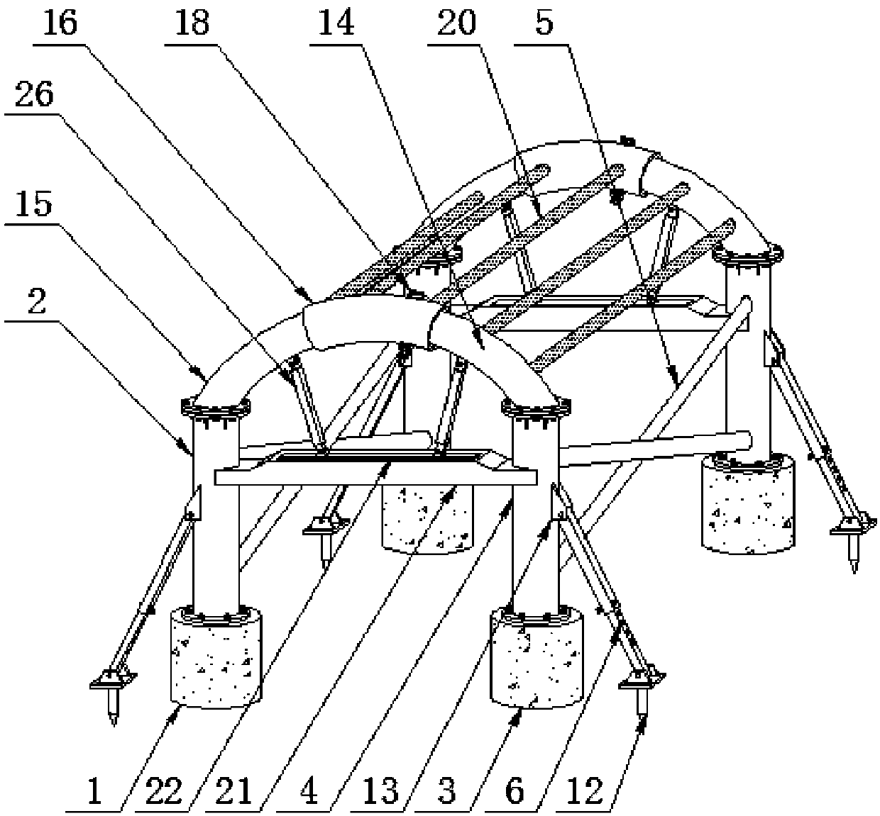
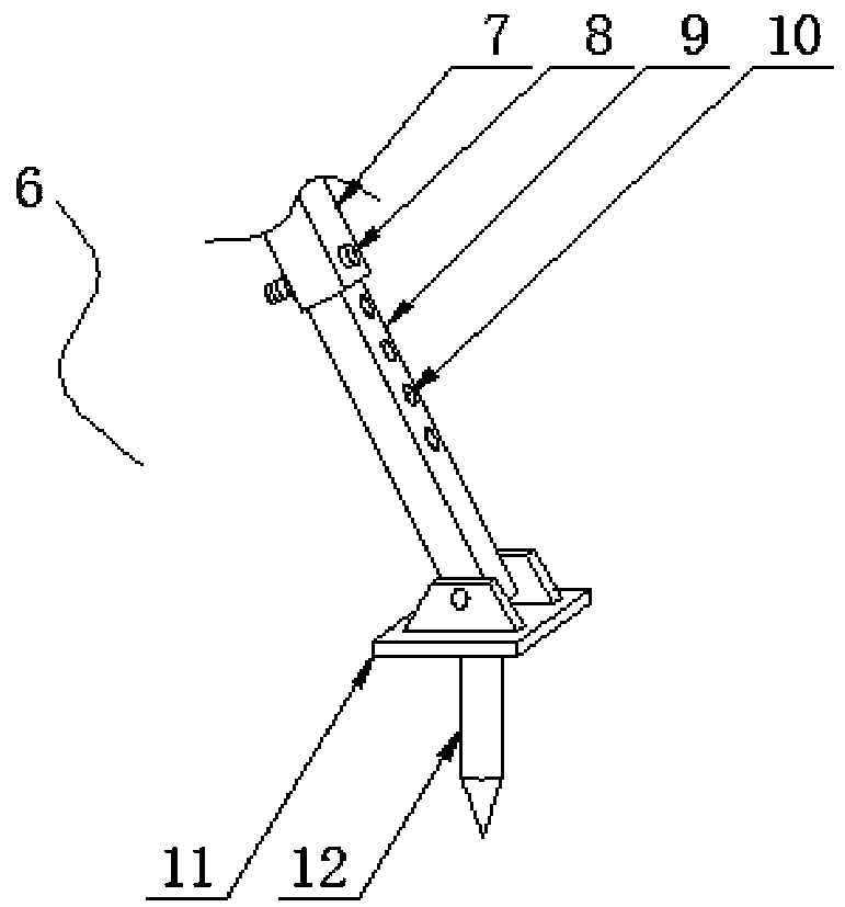
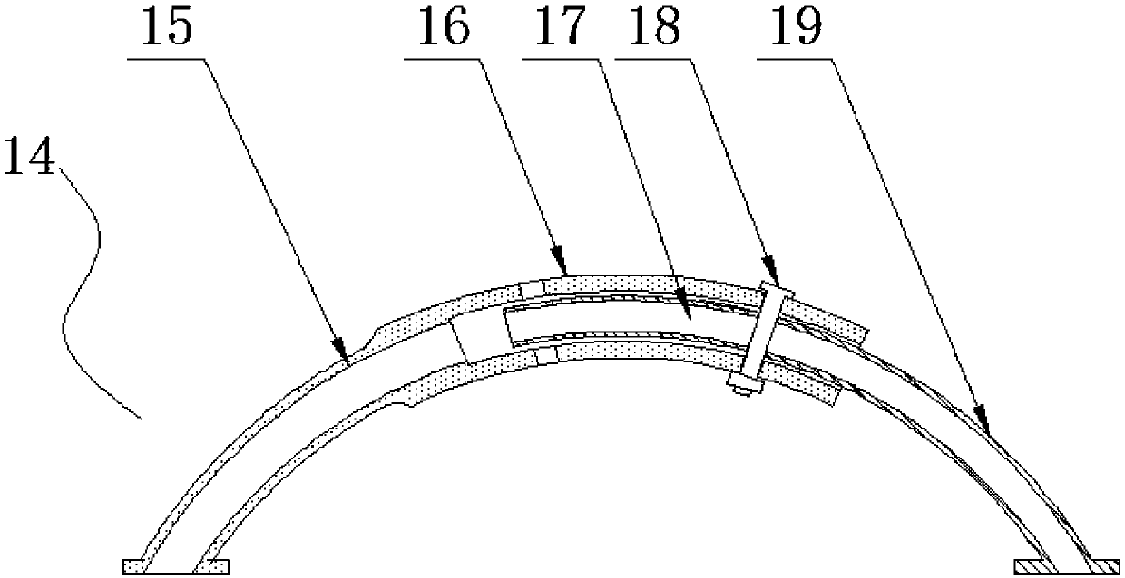
[0029] see Figure 1~5 , in an embodiment of the present invention, a concrete-filled steel tube arch frame for building corridor support includes a transverse frame assembly, a longitudinal bar 20 and an auxiliary support assembly, wherein the transverse frame assembly is within the width of the building corridor direction, and arranged perpendicularly to the longitudinal extension direction of the building corridor, two adjacent transverse frame components are connected by a plurality of longitudinal rods 20 arranged in parallel, and the longitudinal rods are arranged along the length of the building corridor. Extending in the direction, each side of the transverse frame assembly is provided with an auxiliary support assembly extending into and anchored on the ground; it is characterized in that,

[0030] The horizontal frame assembly is an arch structure, and the horizontal frame assembly is a steel pipe concrete structure, and the horizontal frame assembly includes a verti...


PUM


Abstract

The invention discloses a concrete filled steel tube arc frame for supporting an architecture corridor. Supporting assemblies are arranged and can provide diagonal support for the two sides of the arcframe, and thus the overall strength of the arc frame is improved; the supporting assemblies can be adjusted and are suitable for different terrain environments; arc assemblies are arranged, so thatthe arc frame has high bearing capacity and is capable of effectively bearing large impact; buffer assemblies are arranged and can have good buffer effects when first arc parts and second arc parts are impacted, meanwhile, the impact force on the first arc parts and the second arc parts are dispersed, and thus the buffer assemblies have a protection effect on the whole arc frame; the service lifeof the arc frame is prolonged, and the usage safety of the arc frame is improved; tightness adjusting assemblies are arranged, can adjust the buffer support assemblies conveniently, guarantee the supporting tightness, prevent the buffer support assemblies from loosening, and can well provide support especially in a grouting process; anti-loose gear groups are arranged so that wedge blocks can be adjusted to be pressed in conveniently, and convenience is improved.

Description

technical field [0001] The invention relates to the technical field of arches, in particular to a steel pipe concrete arch used for building corridor support. Background technique [0002] In the construction of building corridors, in order to ensure the safety and quality of construction and the smooth progress of construction, some support measures will be taken, and the concrete-filled steel tube arch frame can effectively guarantee the safety during construction. [0003] A Chinese patent discloses a combined steel pipe concrete arch frame for support (authorized announcement number CN206668287U). The arch frame in this patented technology has high bearing capacity, strong bending resistance and deformation resistance, energy saving, safety, and conforms to modern green Environmental protection construction requirements, fast construction speed, short construction period, simple installation, good economic benefits, suitable for a variety of geological conditions and env...

Claims


Application Information

Patent Timeline
Patent Type & Authority Applications(China)
IPC IPC(8): E21D11/10E21D11/22
CPCE21D11/10E21D11/22
Inventor 杨宁赵美霞李昂锦李光耀李飞洪杨虎威于福超刘涛
Owner JIANGSU VOCATIONAL INST OF ARCHITECTURAL TECH
Learn More