EHV diaphragm compressor hydraulic leading seal diaphragm head

A diaphragm compressor and guided technology, which is applied in the direction of mechanical equipment, variable capacity pump components, machines/engines, etc., can solve the problems of space occupation, inability to arrange, and large fastening force, etc., to reduce space occupation and save Space and materials, the effect of uniform force

Pending Publication Date: 2019-03-29
SHENYANG YUANDA COMPRESSOR
View PDF0 Cites 1 Cited by
  • Summary
  • Abstract
  • Description
  • Claims
  • Application Information

AI Technical Summary

Problems solved by technology

[0004] 1. Bolt arrangement is difficult: in order to meet the required pre-tightening force, the number of bolts will increase and the specifications will be larger
When there are too many bolts, it is necessary to enlarge the diameter of the cylinder head. After the diameter increases, in order to ensure sufficient rigidity, the thickness of the cylinder head also needs to be increased, which makes the membrane head bulky, which will cause problems such as waste of materials, difficulty in maintenance, and space occupation, and may even be caused by Too many bolts required to place at all
[0005] 2. Uneven stress: Using bolts to fasten will inevitably lead to a large fastening force at the bolt position, while the fastening force in the middle area between the bolt and the bolt is small, resulting in the need for greater pre-tightening force during

Method used


Image

  • EHV diaphragm compressor hydraulic leading seal diaphragm head
  • EHV diaphragm compressor hydraulic leading seal diaphragm head
  • EHV diaphragm compressor hydraulic leading seal diaphragm head

Examples


Embodiment Construction

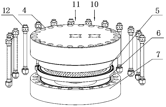
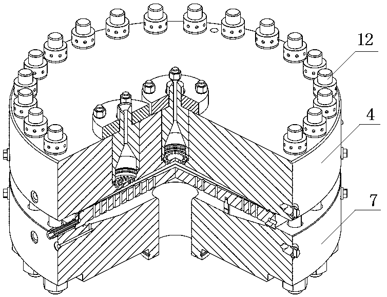
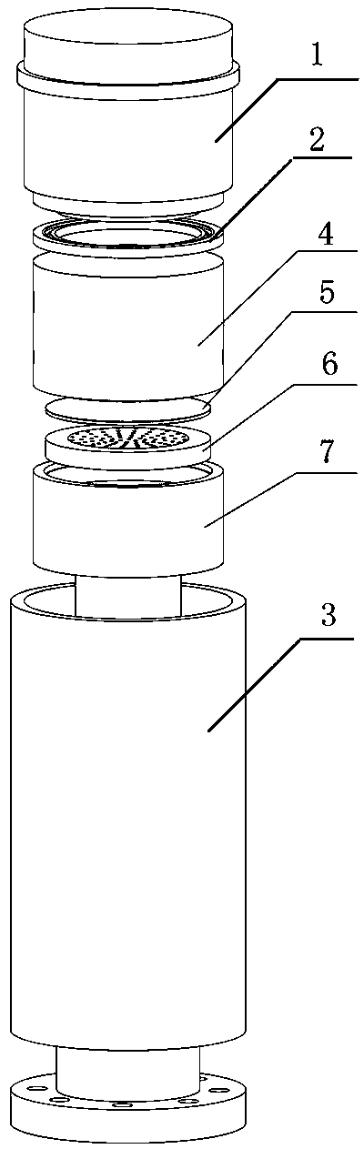
[0026] Such as figure 1 -6 shows the hydraulically guided sealing diaphragm head of the ultra-high pressure diaphragm compressor of the present invention, including the cylinder head 4, the diaphragm 5, the oil distribution plate 6 and the cylinder body 7. The structures and functions of the above components are basically the same as those of the existing ones; It includes a stuffing box 3 for accommodating the above-mentioned parts and a main nut 1 for fastening the parts in the box matched with the stuffing box; in the stuffing box from top to bottom are cylinder head, diaphragm, oil distribution plate and Cylinder body, the cylinder body is in an inverted "convex" shape, which cooperates with the limit table at the lower part of the stuffing box to play the role of limit position; the upper part of the cylinder body is provided with a groove for accommodating the oil distribution plate and the diaphragm, The groove plays the role of accommodating the above-mentioned compone...


PUM


Abstract

The invention discloses an EHV diaphragm compressor hydraulic leading seal diaphragm head, which comprises a cylinder cap, a diaphragm, an oil distribution disk, and a cylinder body, and also comprises a stuffing box and a main nut matched with the stuffing box. The cylinder body is shaped like an inverted Chinese character 'tu', and is matched with the lower part of the stuffing box; an accommodation oil distribution disk and a groove of the diaphragm are arranged at the upper part of the cylinder body, and depth of the groove is less than the total height of the oil distribution disk and thediaphragm; an oil duct is arranged in the middle part of the cylinder body, a piston is arranged in the oil duct, and the piston is connected with a crankshaft of the compressor; an air flue is arranged on the cylinder cap, which is communicated with an air suction inlet and an air vent respectively, the lower end opening of the air flue is positioned under the cylinder cap; a pressure oil inletis also arranged at the side of the cylinder cap, a pressure oil outlet is arranged at a joint gap between the cylinder cap and the main nut above the cylinder cap, and the pressure oil inlet is communicated with the pressure oil outlet; a seal ring is arranged at a joint gap between the cylinder cap and the main nut. The EHV diaphragm compressor hydraulic leading seal diaphragm head solves the problem of difficult bolt arrangement, uneven force and complicated assembly in the prior art.

Description

technical field [0001] The invention belongs to the technical field of compressor structures, and in particular relates to a hydraulically guided sealing diaphragm head of an ultra-high pressure diaphragm compressor. Background technique [0002] The diaphragm head of existing diaphragm compressor is mainly made of cylinder head, diaphragm, oil distribution plate, cylinder block, bolt 12 etc. (such as figure 1 , figure 2 shown). The diaphragm head is sealed with bolt pre-tightening, and the cylinder head and oil distribution plate clamp the diaphragm in the middle with high pre-tightening force through the bolt structure. In order to ensure that the compressed gas is completely discharged when the compressor is running, the hydraulic oil side pressure needs to be 10%-20% higher than the gas side pressure. When the exhaust pressure is high, there is a higher hydraulic pressure between the diaphragm and the cylinder. . According to the sealing principle, in order to ensur...

Claims


Application Information

Patent Timeline
IPC IPC(8): F04B45/04F04B39/00F04B39/12F04B39/14
CPCF04B39/00F04B39/122F04B39/125F04B39/14F04B45/04
Inventor 路伟安俊霖王晓龙郭殿文丛雨飞
Owner SHENYANG YUANDA COMPRESSOR
Why Eureka
Try Eureka