Mounting structure and mounting method of deep well pump pipe in civil air defense room of comprehensive building

A technology of installation structure and installation method, which is applied to the components, pumps, and pump components of the pumping device for elastic fluids, which can solve the problem of cracking of the welding seam connecting the flange and the pump pipe, the small diameter of the wellhead of the deep well pump, and the difficulty in solving the problems. Guarantee water supply performance and other issues to reduce pump maintenance, enhance stability, and avoid swing collisions

Pending Publication Date: 2019-03-29
中国华西企业股份有限公司
View PDF0 Cites 3 Cited by
  • Summary
  • Abstract
  • Description
  • Claims
  • Application Information

AI Technical Summary

Problems solved by technology

[0004] The purpose of the present invention is to provide the installation structure and installation method of the deep well pump pipe in the civil air defense room of the comprehensive building, so as to solve the problem that the diameter of the wellhead of the deep well pump in the civil air defense room in the prior art is small, and it is impossible to install the pipe support in the pipe well, which is very easy to cause the flange and the pump The connecting weld seam of the pipe is pulled and cracked, which leads to high failure rate and short service life, and it is difficult to guarantee the water supply performance of the air defense room in wartime. For the deep well pump with a small wellhead diameter in the air defense room, improve the pump pipe components The structural strength makes the hoisting flexible and convenient, prolongs the running time of the equipment, and saves maintenance costs

Method used


Image

  • Mounting structure and mounting method of deep well pump pipe in civil air defense room of comprehensive building
  • Mounting structure and mounting method of deep well pump pipe in civil air defense room of comprehensive building
  • Mounting structure and mounting method of deep well pump pipe in civil air defense room of comprehensive building

Examples


Embodiment 1

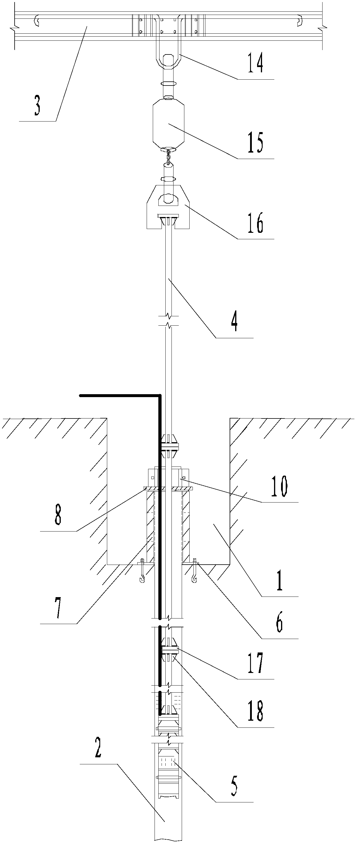
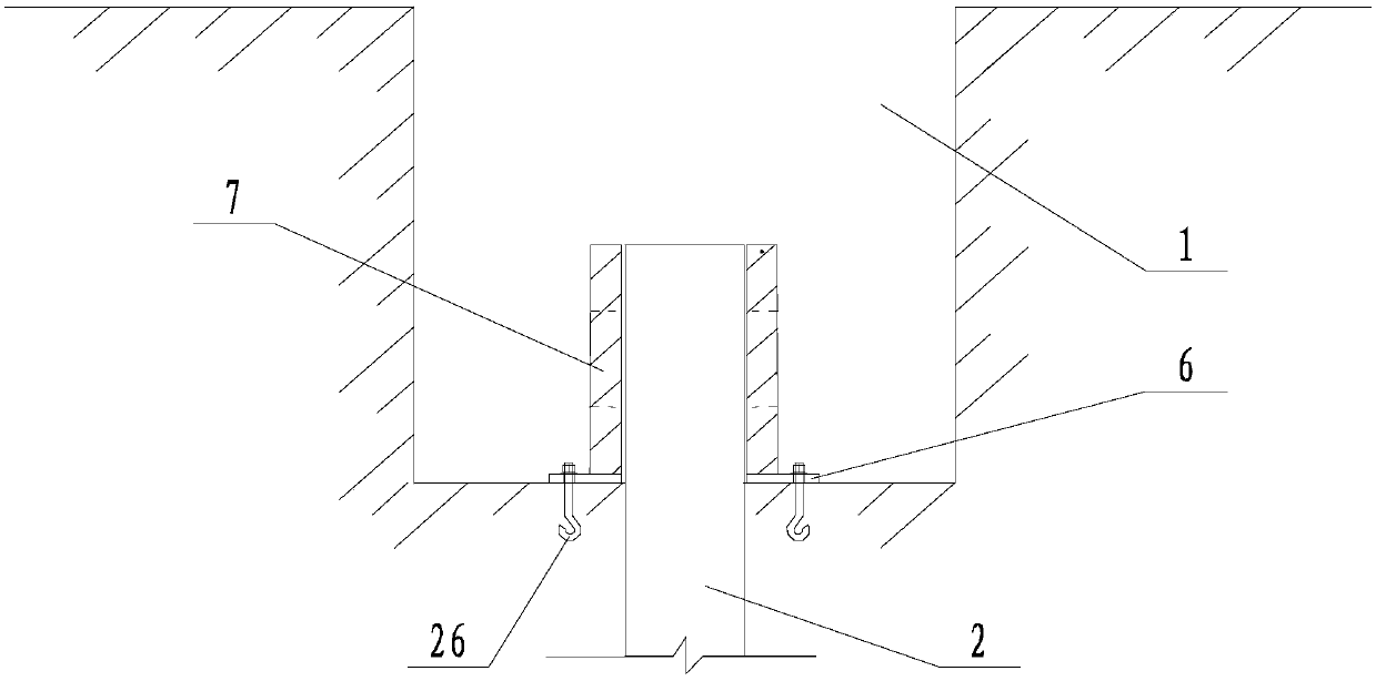
[0040] Such as Figure 1 to Figure 8 The installation structure of the deep well pump pipe in the civil air defense room of the comprehensive building is shown, and the installation structure of the deep well pump pipe in the civil air defense room of the comprehensive building includes the indoor pump pit 1, the deep water well 2 drilled in the pump pit 1, and the structure above the pump pit 1 The plate 3 and the water pump 5 are located in the deep well 2. The cable of the water pump 5 extends out of the pump pit 1 and is connected to the control box of the deep well pump. 4. Pass through the pump pit 1 and enter the deep water well 2. The bottom of the pump pipe 4 is connected to the water pump 5. The wellhead load-bearing frame is arranged in the pump pit 1. The wellhead load-bearing frame includes a first bottom plate 6 anchored at the bottom of the pump pit 1. The load-bearing bracket 7 is welded on the first bottom plate 6, and the load-bearing bracket 7 is used to car...

Embodiment 2

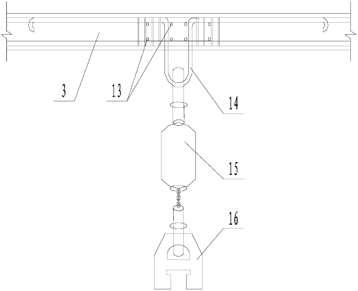
[0043] Such as Figure 1 to Figure 8 As shown, on the basis of Embodiment 1, the hoisting mechanism includes a hidden beam 13 arranged in the structural plate 3, the top end of the hook 14 is pre-buried above the hidden beam 13, and the bottom end of the hook 14 is in the shape of Arc shape, hook 14 is connected with hoist chain 15 , the bottom end of hoist chain 15 is connected with sling 16 , and the sling 16 is used for fixed connection with the top end of pump pipe 4 . The upper and lower ends of the pump pipe 4 are welded with flanges 17, and two adjacent pump pipes 4 are connected by flanges, and four flanges are welded between each flange 17 and the corresponding pump pipe 4. The ribs 18 uniformly distributed in the circumferential direction of the pump pipe 4 . The two flanges 17 between two adjacent sections of the pump pipe 4 are connected by flange bolts 19, and the flange bolts 19 pass through the two ends of the two flanges 17 and are sequentially inserted along ...

Embodiment 3

[0047] The installation method of the deep well pump pipe in the civil air defense room of a complex building comprises the following steps: (a) digging a pump pit 1 in the civil air defense room, drilling a deep water well 2 in the pump pit 1 to the design well depth, and placing the pump pipe on the structural plate 3 above the pump pit 1 A hoisting mechanism is provided to anchor the first bottom plate 6 to the bottom of the pump pit 1; (b) an anti-swing mechanism is set at the upper and lower ends of the water pump 5, and the anti-sway mechanism includes a ring clamp 11 sleeved on the outside of the water pump 5 , a number of leaf springs 12 are evenly distributed in the outer ring of the ring clamp 11, and the spring leaf 12 is arc-shaped, so that the concave surface of the spring leaf 12 faces the direction of the water pump 5; the water pump 5 with the anti-shake mechanism installed is connected to one end of the pump The pipe is lowered into the deep-water well 2 throug...


PUM


Abstract

The invention discloses a mounting structure and a mounting method of a deep well pump pipe in a civil air defense room of a comprehensive building. the pump pipe passes through a pump pit and entersa deep water well. The bottom of the pump pipe is connected to a water pump. A well head bearing frame, a second bottom plate and holt hoop iron above the second bottom plate are arranged in the pumppit. The holt hoop iron has two halves. The two halves of the holt hoop iron are connected to each other by bolts, and one of the two halves is welded to the second bottom plate. Anti-sway spring mechanisms are connected to the upper and lower ends of the water pump. The mounting structure and mounting method solve the problem in the prior art that the diameter of the well head of a deep well pumpin a civil air defense room is narrow, a construction work cannot enter to mount a pipeline bracket, and joint welds between a flange and the pump pipe are prone to crack, thereby resulting in high failure rate, short service life and difficult guarantee of water supply performance in the civil air defense room during wartime, improve the structure strength of the pump pipe member for the deep well pump with narrow wellhead diameter in the civil air defense room, make the lifting and assembling flexible and convenient, prolong the running time of the equipment, and save the maintenance cost.

Description

technical field [0001] The invention relates to the field of large-scale civil air defense facilities, in particular to an installation structure and an installation method of deep well pump pipes in the civil air defense indoor of a comprehensive building. Background technique [0002] Civil air defense projects, also known as civil air defense fortifications, refer to underground protective buildings built separately to protect personnel and material shelter, civil air defense command, and medical rescue in wartime, as well as basements built in combination with ground buildings that can be used for air defense during wartime. The civil air defense project is an important facility to prevent sudden enemy attacks, effectively cover personnel and materials, and preserve war potential; it is an engineering guarantee to persist in urban combat and long-term support for anti-aggression wars until victory. The newly-built civil air defense projects have undergone feasibility dem...

Claims


Application Information

Patent Timeline
Patent Type & Authority Applications(China)
IPC IPC(8): F04D29/62F04D29/66F04D29/00
CPCF04D29/628F04D29/007F04D29/669
Inventor 杨军刘天华邓贤刚刘春李宇舟郑云德陈炜王翔杨恒石磊李阳
Owner 中国华西企业股份有限公司
Why Eureka
Try Eureka