Automatic heating battery cell diaphragm rotary shaft device

A rotating shaft device, self-heating technology, applied in heating devices, lighting and heating equipment, circuits, etc., can solve the problems of low production efficiency, low production efficiency, difficult to control oven temperature, etc., to ensure the quality of heating and drying, heating High drying efficiency and the effect of meeting drying requirements

Pending Publication Date: 2019-03-29
ZHENJIANG CINNIC AUTOMATIC TECH CO LTD
View PDF7 Cites 1 Cited by
  • Summary
  • Abstract
  • Description
  • Claims
  • Application Information

AI Technical Summary

Problems solved by technology

Due to the particularity of the diaphragm material, especially the ceramic diaphragm, due to its high water content, it takes a long time to dry, and the temperature of the oven is difficult to control, resulting in low production efficiency
[0004] Before the cell lamination process, the cell separator needs to be processed to remove excess water. Since the base film of the cell separator has a water content of 500ppm when it leaves the factory, the ceramic base film can reach 1000ppm. Therefore, the existing processing method The cell separator needs to be placed in a low-humidity room for at least 24 hours to remove excess moisture. This process is time-consuming and laborious, resulting in low production efficiency

Method used


Image

  • Automatic heating battery cell diaphragm rotary shaft device
  • Automatic heating battery cell diaphragm rotary shaft device
  • Automatic heating battery cell diaphragm rotary shaft device

Examples


Embodiment Construction

[0024] The present invention will be further illustrated below in conjunction with the accompanying drawings and specific embodiments, and it should be understood that these embodiments are only for illustrating the present invention and are not intended to limit the scope of the present invention.

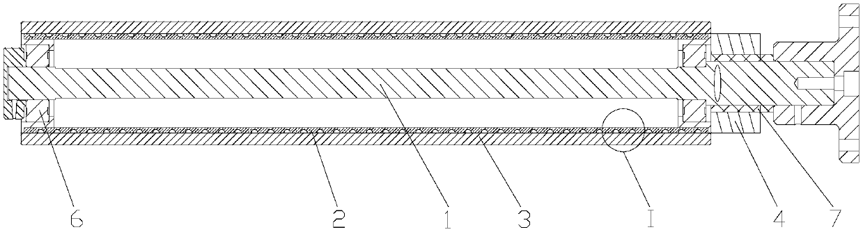
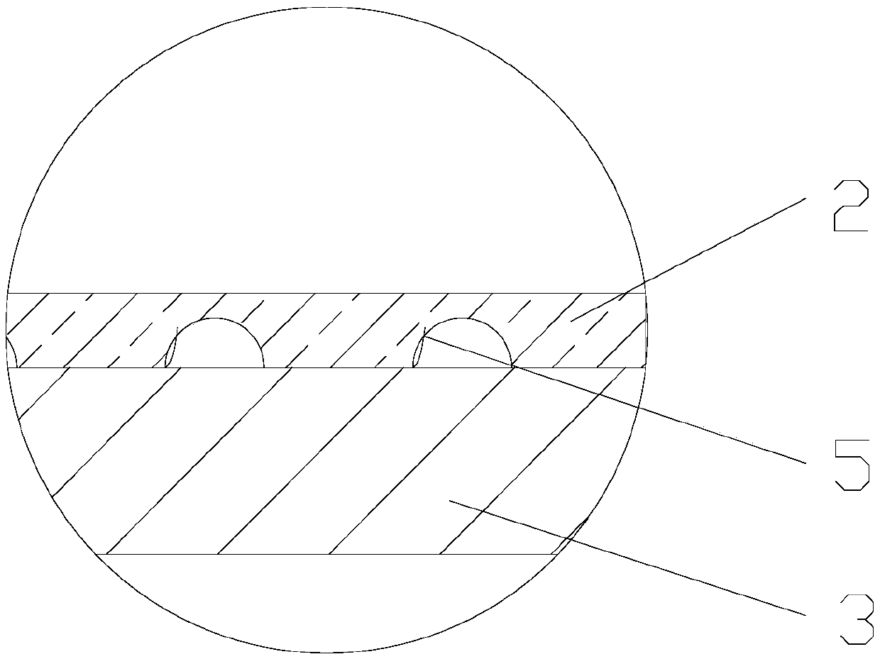
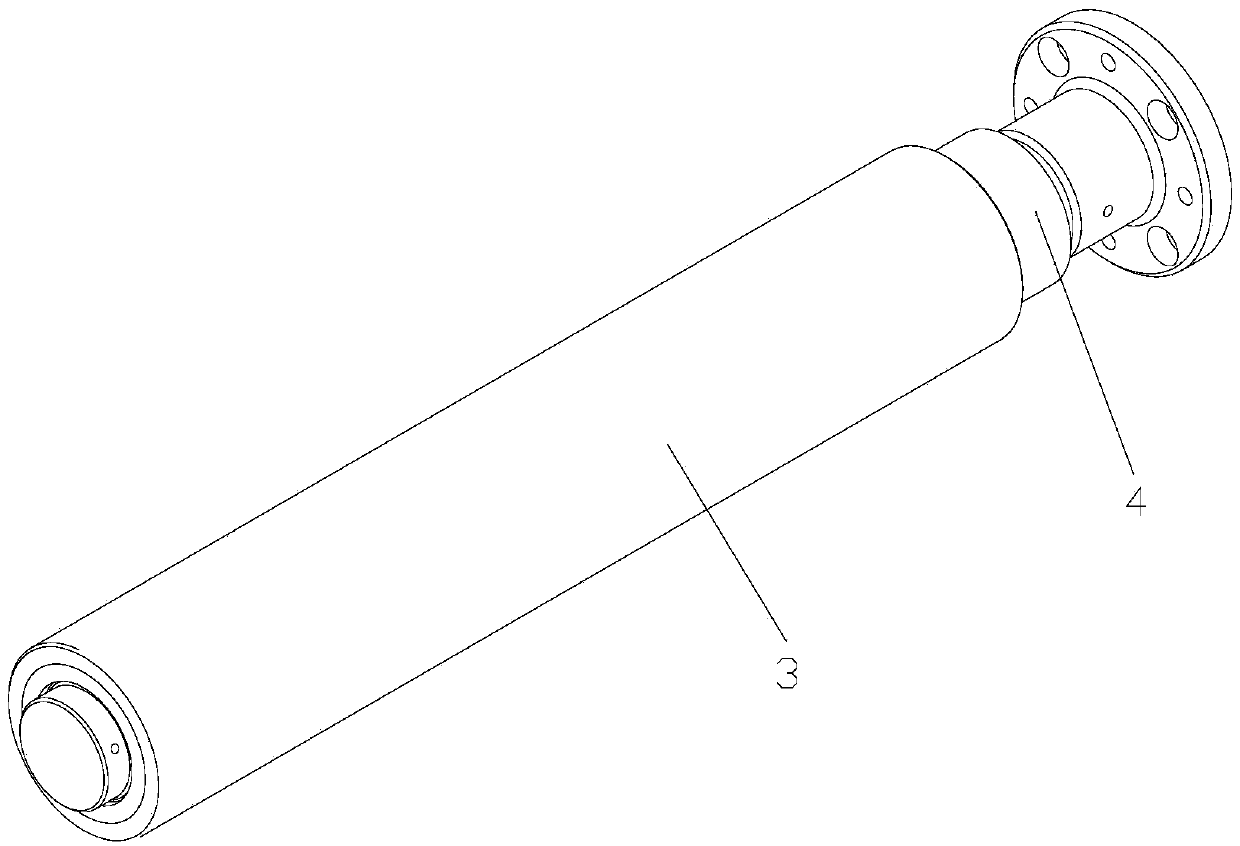
[0025] A self-heating type cell diaphragm rotating shaft device, such as Figure 1~3 As shown, it includes a central shaft 1, a heating shaft 2, an outer shaft 3, a rotating conductive ring 4, a heating wire 5, a controller, a bearing 6, a sensor, and a shaft sleeve 7. The sensor is a thermocouple sensor, and the controller is a PID controller.

[0026] The two ends of the central shaft 1 are fixed, and the two ends of the central shaft 1 can be fixedly connected with other devices through the shaft fixing seat. The heating shaft 2 is sleeved on the central shaft 1, and the two ends of the heating shaft 2 are respectively connected to the central shaft 1 through a bearing 6. The b...


PUM


Abstract

The invention discloses an automatic heating battery cell diaphragm rotary shaft device. The automatic heating battery cell diaphragm rotary shaft device comprises a center shaft, a heating shaft, anouter shaft, a rotary conducting ring, heating wires and a controller, wherein two ends of the center shaft are fixed; the heating shaft is arranged on the center shaft in a sleeving mode; the two ends of the heating shaft are connected to the center shaft separately through a bearing; the heater wires are wound around outer circumference of the heating shaft; the outer shaft is fixedly connectedwith the heating shaft in a sleeving mode; the rotary conducting ring at one side of the outer shaft sleeves and is connected with the center shaft; the heater wires and the controller are respectively connected with the rotary conducting ring by signals. The advantages of the automatic heating battery cell diaphragm rotary shaft device are that through arrangements of the heating shaft and the heater wires and allocation of the rotary conducting ring, the battery cell diaphragm can be heated and dried synchronously while being wound around the automatic heating battery cell diaphragm rotary shaft device, so that the processing step of placing the battery cell diaphragm in an oven or low-humidity room for dewatering and drying is omitted, the production time of power batteries is shortenedto a great extent and production efficiency is improved.

Description

technical field [0001] The invention relates to a rotating shaft device, in particular to a self-heating electric core diaphragm rotating shaft device. Background technique [0002] In the process of production and processing of power lithium batteries, the cell diaphragm needs to be dehydrated and dried before performing such as cell diaphragm winding or cell lamination processing. [0003] Before the cell separator is wound, the cell separator needs to be dried to remove excess water. The existing drying process is oven drying. Due to the particularity of the diaphragm material, especially the ceramic diaphragm, due to its high water content, it takes a long time to dry, and the temperature of the oven is difficult to control, resulting in low production efficiency. [0004] Before the cell lamination process, the cell separator needs to be processed to remove excess water. Since the base film of the cell separator has a water content of 500ppm when it leaves the factory,...

Claims


Application Information

Patent Timeline
Patent Type & Authority Applications(China)
IPC IPC(8): F26B13/18F26B23/06H01M2/14H01M50/403
CPCF26B13/18F26B23/06H01M50/403Y02E60/10
Inventor 陈红伟吉跃华袁伟宏贝维学贡建峰
Owner ZHENJIANG CINNIC AUTOMATIC TECH CO LTD
Why Eureka
Try Eureka