
A heat pump device for sludge drying

A technology of sludge drying and heat pump device, applied in the direction of dewatering/drying/concentrating sludge treatment, etc., can solve the problems of unfavorable smooth operation of heat pump drying, unable to meet the requirements of sludge drying, low utilization rate of thermal efficiency, etc. To achieve the effect of compact structure, conducive to smooth operation, and improve the utilization rate of thermal efficiency

Active Publication Date: 2021-08-06
天津五洲同创空调制冷设备有限公司
View PDF5 Cites 2 Cited by
  • Summary
  • Abstract
  • Description
  • Claims
  • Application Information

AI Technical Summary

Problems solved by technology

However, the heat pump device used for sludge drying at this stage has the problems of low thermal efficiency utilization rate and serious heat loss, which is not conducive to the smooth operation of heat pump drying and cannot meet the sludge drying requirements

Method used


Image

  • A heat pump device for sludge drying

Examples


Embodiment 1

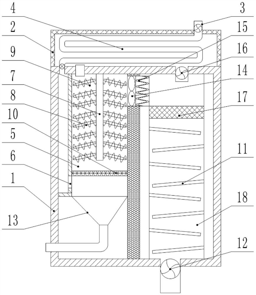
[0023]A heat pump device for sludge drying, comprising a shell 1, characterized in that a heat recovery box 2 is fixedly connected to the top of the shell 1, and an asbestos heat insulation sleeve is covered on the outer wall of the shell 1. The inner wall of the heat recovery box 2 is fitted with a thermal insulation board, and the heat recovery box 2 is arranged in a hollow cuboid structure, and the top side of the heat recovery box 2 is provided with a hot and humid air inlet pipe 3. The air outlet end of the hot and humid air inlet pipe 3 runs through the top of the heat recovery box 2 and is connected with a heat recovery pipe 4. The heat recovery pipe 4 is located inside the heat recovery box 2 and is arranged in a serpentine structure from top to bottom. The air outlet end of the heat recovery pipe 4 runs through the top of the housing 1 and communicates with the inside of the housing 1, and the hot and humid air inlet pipe 3 and the air outlet end of the heat recovery p...


PUM


Abstract

The present invention is a heat pump device for sludge drying, which includes a shell, and is characterized in that a heat recovery box is fixedly connected to the top of the shell, and the heat recovery box is arranged in a hollow cuboid structure, located on the In the heating chamber below the gas distribution plate two, a number of electric heating rods inclined downward are interlaced from top to bottom. The invention has compact structure and reasonable design. By setting the serpentine heat recovery pipe and the heat recovery box, the heat lost by the hot and humid air into the pipe can be effectively recovered, and the thermal efficiency utilization rate can be improved. Gas distribution plate 1, cooling plate and condensate net, uniformly condense and dehumidify the hot and humid air, preheat by setting electric heating wires, set gas distribution plate 2 in the heating and heating chamber, and set the tilt mutually staggered from top to bottom The downward electric heating rod evenly heats the dehumidified air, which is conducive to the stable operation of the heat pump drying and meets the sludge drying requirements.

Description

technical field [0001] The invention relates to the technical field of heat pumps, in particular to a heat pump device for sludge drying. Background technique [0002] Municipal sludge is a high-moisture sediment produced in the process of urban sewage treatment. It is a mixture of organic matter and inorganic matter with a high water content. Sludge heat pump dryer is the main equipment for sludge drying treatment. Heat pump drying technology is a recognized green drying technology. After the hot air with high temperature and low humidity discharged from the condenser passes over the wet sludge, it becomes The relative humidity of high humid and hot gas is generally between 70% and 80%. The hot and humid gas passes through the evaporator, and the water vapor condenses out of the system. Among them, the heat pump device is one of the indispensable and important equipment in the sludge heat pump dryer. However, the heat pump device used for sludge drying at this stage has ...

Claims


Application Information

Patent Timeline
Patent Type & Authority Patents(China)
IPC IPC(8): C02F11/13
CPCC02F11/12
Inventor 郭振明郭振军周振壮陈立贞贾双伟黄有利
Owner 天津五洲同创空调制冷设备有限公司
Learn More