A solid oxidation testing device and its application
A testing device and oxidizing technology, which is applied in the direction of chemical analysis by combustion and thermal development of materials, etc., can solve the problems of large error in experimental results and poor experimental accuracy, and achieve the effect of simple device and reliable experimental results
- Summary
- Abstract
- Description
- Claims
- Application Information
AI Technical Summary
Problems solved by technology
Method used
Image
Examples
Embodiment 1
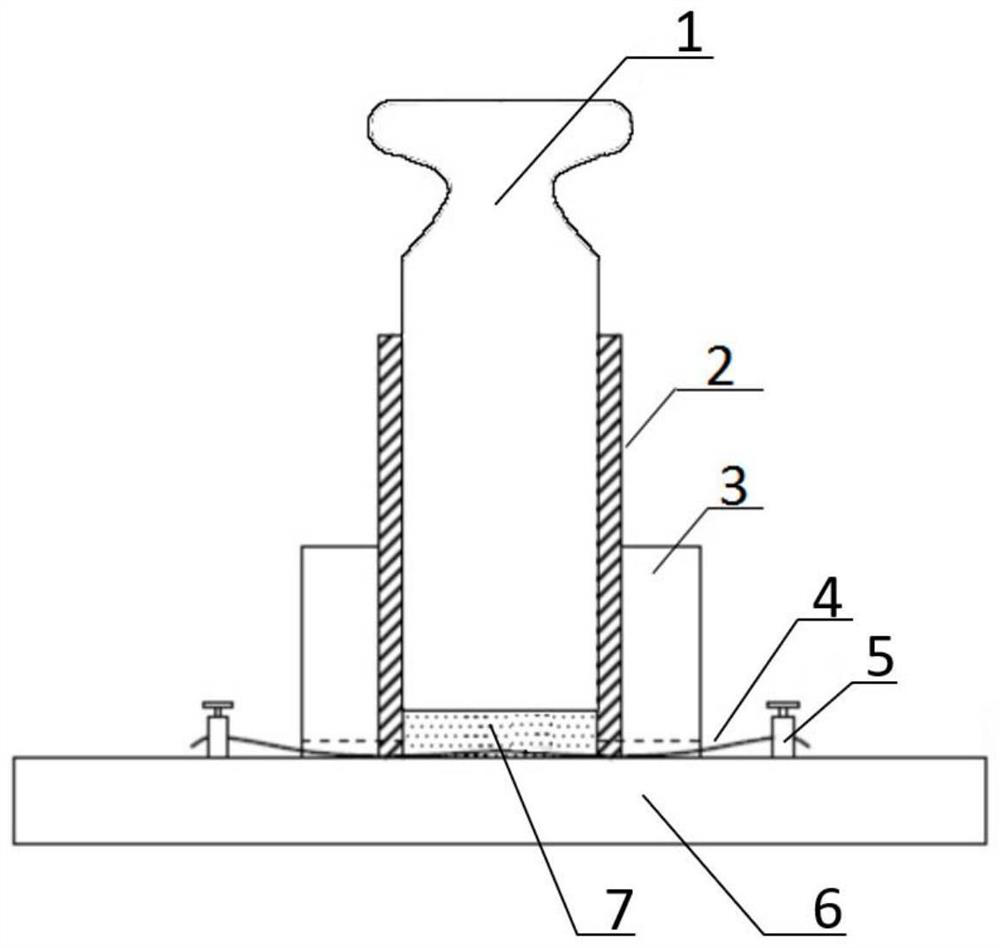
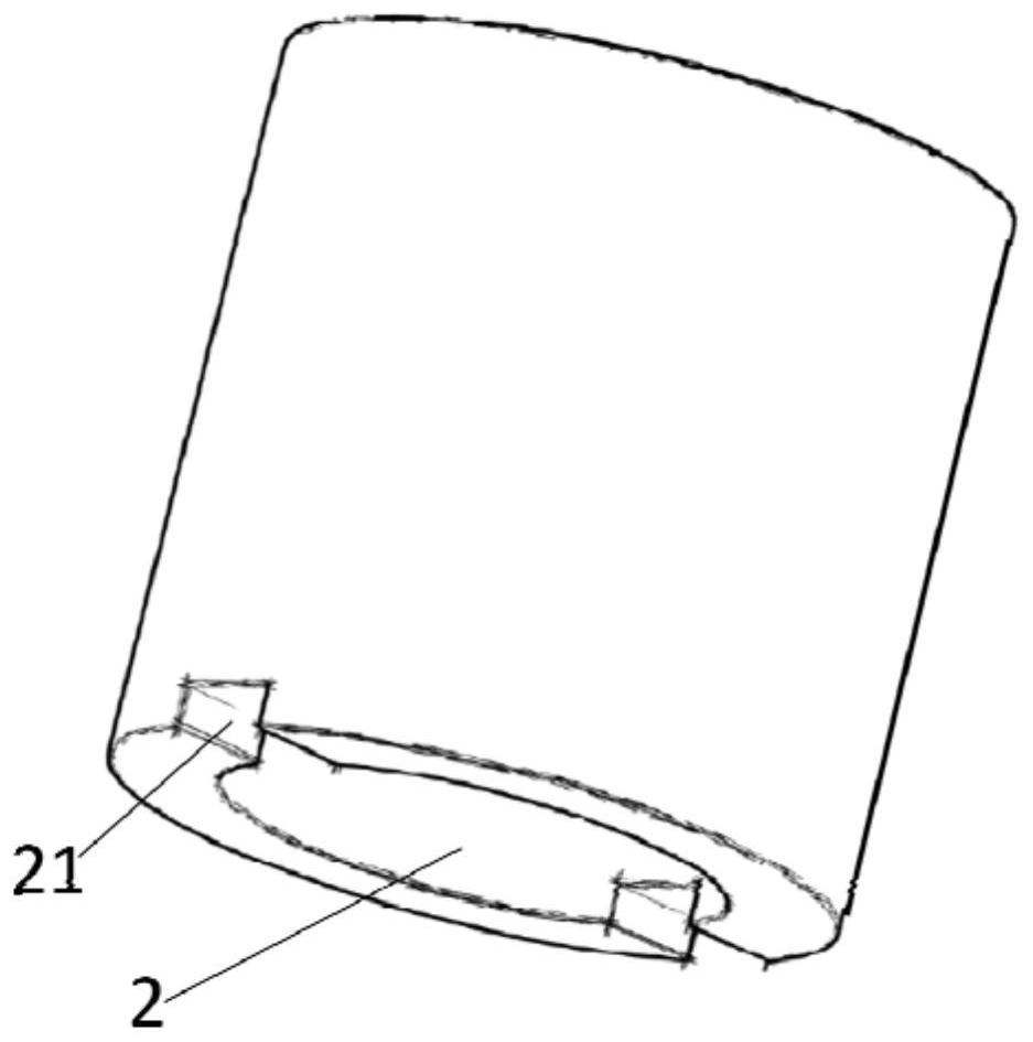
[0030] A solid oxidation test device, such as figure 1 As shown, it includes bottom ceramic plate 6, heating wire 4, terminal 5, metal plug 1, ceramic ring 3, metal cylinder 2 and infrared thermometer; terminal 5 is placed on the bottom ceramic plate 6, and connected with DC power supply Connection, the two ends of the heating wire 4 are connected to the terminal 5, and buried under the solid test sample mixture 7; the metal plug 1 is installed in the metal cylinder 2, the metal cylinder is installed in the ceramic ring 3, and the metal plug The outer wall is in contact with the inner wall of the metal cylinder, and the outer wall of the metal cylinder is in contact with the inner wall of the porcelain ring. The structure of the metal cylinder 2 is as figure 2 As shown, the diameter of the bottom end is provided with a symmetrical metal cylinder gap 21. The bottom structure of the ceramic ring 3 is the same as that of the metal cylinder, and a symmetrical ceramic ring gap is...
Embodiment 2
[0040] A solid oxidation test device, such as figure 1 As shown, it includes bottom ceramic plate 6, heating wire 4, terminal 5, metal plug 1, ceramic ring 3, metal cylinder 2 and infrared thermometer; terminal 5 is placed on the bottom ceramic plate 6, and connected with DC power supply Connection, the two ends of the heating wire 4 are connected to the terminal 5, and buried under the solid test sample mixture 7; the metal plug 1 is installed in the metal cylinder 2, the metal cylinder is installed in the ceramic ring 3, and the metal plug The outer wall is in contact with the inner wall of the metal cylinder, and the outer wall of the metal cylinder is in contact with the inner wall of the porcelain ring. The structure of the metal cylinder 2 is as figure 2 As shown, the diameter of the bottom end is provided with a symmetrical metal cylinder gap 21. The bottom structure of the ceramic ring 3 is the same as that of the metal cylinder, and a symmetrical ceramic ring gap is...
Embodiment 3
[0044] A solid oxidation test device, such as figure 1As shown, it includes a bottom ceramic plate 6, a heating wire 4, a terminal 5, a metal plug 1, a ceramic ring 3, a metal cylinder 2 and an infrared thermometer; the terminal 5 is placed on the bottom ceramic plate 6, and connected to a DC Connected, the two ends of the heating wire 4 are connected to the terminal 5, and buried under the solid test sample mixture 7; the metal plug 1 is installed in the metal cylinder 2, the metal cylinder is installed in the ceramic ring 3, and the metal plug The outer wall is in contact with the inner wall of the metal cylinder, and the outer wall of the metal cylinder is in contact with the inner wall of the porcelain ring. The structure of the metal cylinder 2 is as figure 2 As shown, the diameter of the bottom end is provided with a symmetrical metal cylinder gap 21, and the bottom structure of the ceramic ring 3 is the same as that of the metal cylinder, and a symmetrical ceramic rin...
PUM
| Property | Measurement | Unit |
|---|---|---|
| thickness | aaaaa | aaaaa |
Abstract
Description
Claims
Application Information
 - R&D
- Intellectual Property
- Life Sciences
- Materials
- Tech Scout
- Unparalleled Data Quality
- Higher Quality Content
- 60% Fewer Hallucinations
Browse by: Latest US Patents, China's latest patents, Technical Efficacy Thesaurus, Application Domain, Technology Topic, Popular Technical Reports.
© 2025 PatSnap. All rights reserved.Legal|Privacy policy|Modern Slavery Act Transparency Statement|Sitemap|About US| Contact US: help@patsnap.com


