
Imaging device used for cerebrovascular image segmentation

An image segmentation and imaging device technology, applied in the field of medical devices, can solve the problems of poor fixation effect of cerebral blood vessel images, easy to affect imaging effect, large heat dissipation and energy consumption, etc., and achieves good dustproof and heat dissipation effect, good heat dissipation effect, The effect of saving energy costs

Active Publication Date: 2019-03-29
聊城大学东昌学院
View PDF7 Cites 0 Cited by
  • Summary
  • Abstract
  • Description
  • Claims
  • Application Information

AI Technical Summary

Problems solved by technology

Since the existing cerebrovascular image segmentation imaging device has many working modules, the heat dissipation of the body is relatively large during operation. In order to ensure the segmentation imaging effect of the device on the cerebrovascular image map, it is necessary to perform good ventilation and heat dissipation on the body. The heat dissipation method of the body is usually to open more heat dissipation holes on the side wall of the chassis or install a fan for forced air cooling. Although the heat dissipation holes on the side wall of the chassis can ensure the ventilation effect of the body, it is easy to cause external dust to enter and accumulate through the heat dissipation holes. The surface of the body makes the body warm up faster when working; the use of additional fans for forced air cooling consumes a lot of energy and is not easy to install; and the existing cerebrovascular image segmentation imaging device has a poor fixation effect on the cerebrovascular image. Cerebrovascular images are prone to shift due to the vibration of the body during the segmentation imaging process, which can easily affect the imaging effect

Method used


Image

  • Imaging device used for cerebrovascular image segmentation
  • Imaging device used for cerebrovascular image segmentation
  • Imaging device used for cerebrovascular image segmentation

Examples


Embodiment

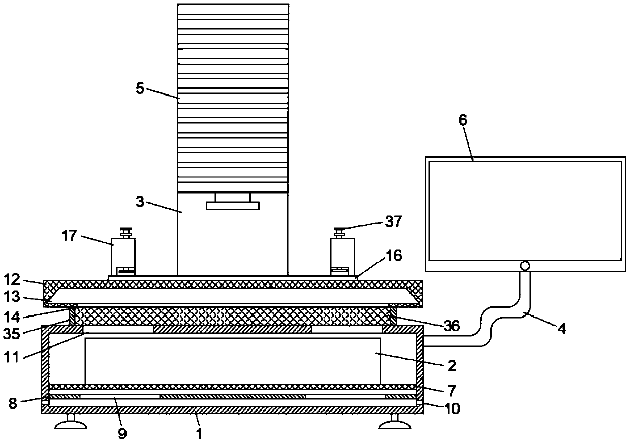
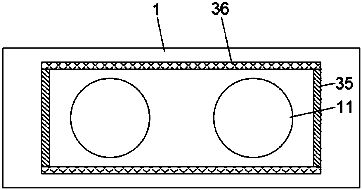
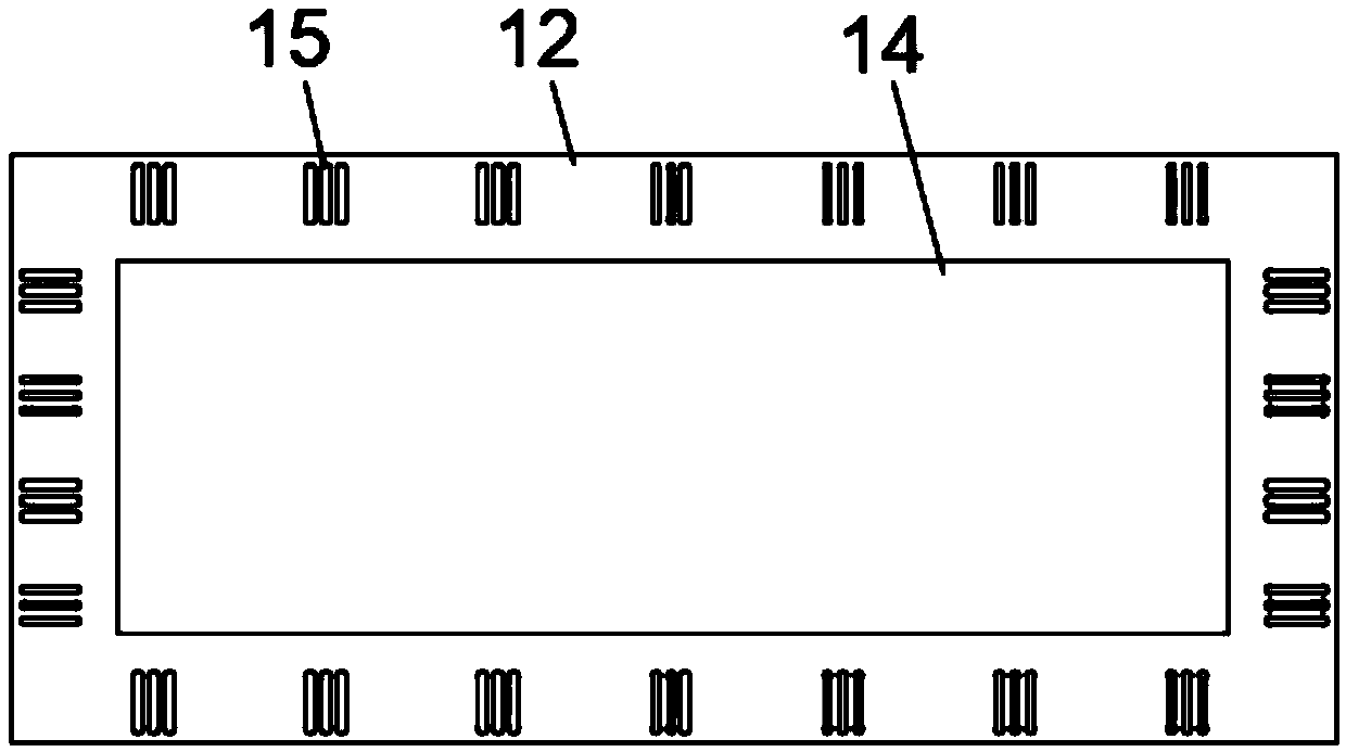
[0024] refer to Figure 1-5 , an imaging device for cerebrovascular image segmentation, comprising a chassis 1, a body 2 is arranged inside the chassis 1, a first bracket 3 and a second bracket 4 are fixedly connected to the outer wall of the chassis 1, and an image is fixedly installed on the upper end of the first bracket 3 instrument 5, a display 6 is fixedly installed on the upper end of the second bracket 4, and the body 2 is electrically connected to the imager 5 and the display 6, and a mounting plate 7 is fixedly connected inside the chassis 1, and the body 2 is fixedly mounted on the mounting plate 7, The inner wall of the chassis 1 below the mounting plate 7 is also fixed with a horizontal partition 8, the surface of the partition 8 is provided with two first cooling holes 9, and the side walls on both sides of the cabinet 1 below the partition 8 are opened. There is a second heat dissipation hole 10 used in conjunction with the first heat dissipation hole 9, and two...


PUM


Abstract

The invention discloses an imaging device used for cerebrovascular image segmentation. The imaging device comprises a chassis. A machine body is arranged in the chassis. The outer wall of the chassisis fixedly connected with a first bracket and a second bracket. A projector is fixedly arranged on the upper end of the first bracket. A display is fixedly arranged on the upper end of the second bracket. The inside of the chassis is fixedly connected with a mounting plate. The inner wall of the chassis below the mounting plate is fixedly connected with a horizontally arranged partition. Two firstheat dissipation holes are arranged in the surface of the partition. According to the invention, the machine body in the chassis is naturally ventilated and radiated, and at the same time external dust is prevented from entering the chassis and accumulating on the surface of the machine body from the heat dissipation holes; the effects of dust prevention and heat dissipation are better; the energy consumption cost of using a fan for forced air cooling can be saved; a cerebrovascular shadowgraph can be better fixed; the operation is convenient; the process of image segmentation and imaging ofthe cerebrovascular shadowgraph is more stable and accurate.

Description

technical field [0001] The invention relates to the technical field of medical devices, in particular to an imaging device for cerebrovascular image segmentation. Background technique [0002] Vascular imaging is an important method based on computer-aided diagnosis and interventional therapy of cardiovascular and cerebrovascular diseases, surgical navigation and postoperative observation. In the vascular analysis system, the segmentation of vascular images is the prerequisite for quantitative description of the shape and scale of blood vessels, and segmentation plays a key role in objectively and accurately quantifying the degree of vascular lesions. Image segmentation is also the basis for vascular structure matching and 3D reconstruction. [0003] Nowadays, the imaging of cerebrovascular image segmentation usually requires multiple working modules such as a computer collaborative imager to segment and analyze the cerebrovascular image, and then import it into the display...

Claims


Application Information

Patent Timeline
IPC IPC(8): G02B27/02H05K7/20
CPCG02B27/022G02B27/026H05K7/20127
Inventor 王运成赵桂清王娟
Owner 聊城大学东昌学院
Features
  • Generate Ideas
  • Intellectual Property
  • Life Sciences
  • Materials
  • Tech Scout
  • Unparalleled Data Quality
  • Higher Quality Content
  • 60% Fewer Hallucinations
Learn More