Mask plate, liquid crystal panel and liquid crystal display device

A technology of mask plate and semi-permeable film, which is applied in the field of liquid crystal panel and liquid crystal display device and mask plate, and can solve the problems of loss of switching function, inability to fully expose the channel, and photoresist leftover, etc.

Active Publication Date: 2021-08-24
HKC CORP LTD
View PDF12 Cites 0 Cited by
  • Summary
  • Abstract
  • Description
  • Claims
  • Application Information

AI Technical Summary

Problems solved by technology

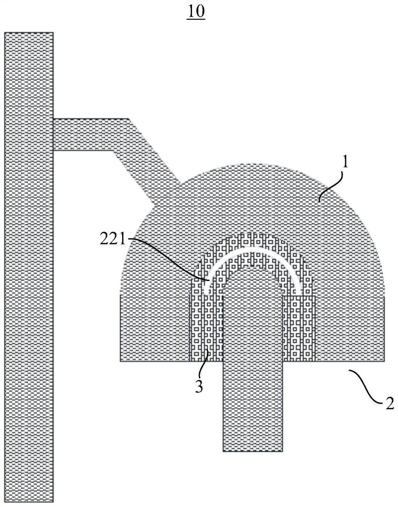
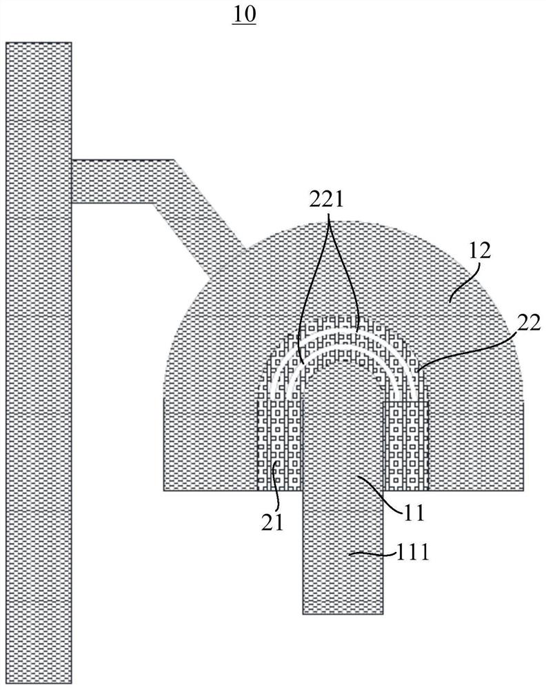
In the actual production process, since the arc area of ​​the channel semi-permeable film is surrounded by opaque areas and semi-permeable film areas, while the straight line area is adjacent to the light-transmitting area, because the light has a certain scattering effect, in the process To ensure that the linear area can complete the exposure of the semi-permeable film, there will be a certain probability of defocus (out of focus) in the arc-shaped area, resulting in the arc-shaped channel of the semi-permeable film cannot be fully exposed, so that the photoresist is completely left, no The method has a semi-protective effect, so that the source and drain of the metal are connected together, and the Thin Film Transistor (TFT, thin film transistor) loses its switching function

Method used


Image

  • Mask plate, liquid crystal panel and liquid crystal display device
  • Mask plate, liquid crystal panel and liquid crystal display device
  • Mask plate, liquid crystal panel and liquid crystal display device

Examples


Embodiment Construction

[0030] The following will clearly and completely describe the technical solutions in the embodiments of the present invention with reference to the accompanying drawings in the embodiments of the present invention. Obviously, the described embodiments are only part of the embodiments of the present invention, not all of them. Based on the embodiments of the present invention, all other embodiments obtained by persons of ordinary skill in the art without creative efforts fall within the protection scope of the present invention.

[0031] It should be noted that if there is a directional indication (such as up, down, left, right, front, back...) in the embodiment of the present invention, the directional indication is only used to explain the position in a certain posture (as shown in the accompanying drawing). If the specific posture changes, the directional indication will also change accordingly.

[0032] In addition, if there are descriptions involving "first", "second" and ...


PUM

PropertyMeasurementUnit
transmittivityaaaaaaaaaa

Abstract

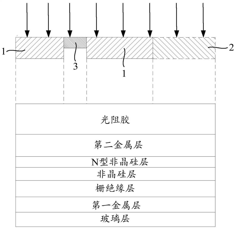
The invention discloses a mask plate, a liquid crystal panel and a liquid crystal display device, wherein the mask plate includes: a light-shielding area, a full light-transmitting area, and a semi-light-transmitting area; the full light-transmitting area is set adjacent to the light-shielding area; Set adjacent to the light-shielding area, and the semi-transparent area includes a first area and a second area, the first area is also set adjacent to the fully light-transmitting area, and the second area is surrounded by the first area and the light-shielding area; the second area has The light-transmitting slit, the width of the light-transmitting slit is smaller than the exposure accuracy of the exposure machine. The reticle of the present invention provides a light-transmitting slit on the second area surrounded by the first area of ​​the semi-transparent area and the light-shielding area, so that the width of the light-transmitting slit is smaller than the exposure accuracy of the exposure machine, and there will be no In the case of small gaps in the exposure area, the amount of light entering the second area can be increased. In this way, the out-of-focus phenomenon during the exposure of the second area can be reduced, and the process yield rate can be improved.

Description

technical field [0001] The invention relates to the field of liquid crystal display, in particular to a mask plate, a liquid crystal panel and a liquid crystal display device. Background technique [0002] The statements herein merely provide background information related to the present application and do not necessarily constitute prior art. Liquid crystal displays occupy an increasingly important position in flat panel displays. At present, four photolithography techniques (4Mask) are used in the production of Twisted Nematic (TN, twisted nematic) or Vertical Alignment (VA, vertical alignment) type liquid crystal panels. Four photolithography refers to five photolithography ( In 5Mask), the lithography of non-metal layer amorphous silicon and n+ amorphous silicon and the lithography of drain and source are combined, and the Indium Tin Oxides (indium tin oxide) film is made at the end. The method of punching a contact hole to realize the connection between the ITO film a...

Claims


Application Information

Patent Timeline
Patent Type & Authority Patents(China)
IPC IPC(8): G02F1/13G02F1/1362G03F1/32
CPCG02F1/1303G02F1/1362G03F1/32
Inventor 吴川
Owner HKC CORP LTD
Why Eureka
Try Eureka