

Robotic operating arm for fundus retinal microsurgery
A technology of microsurgery and robotics, which is applied in ophthalmic surgery, surgical manipulators, surgical robots, etc., can solve the problems of poor accuracy and stability of surgical operations, and achieve the effects of eliminating physiological tremors, improving consistency, and determining simplicity
- Summary
- Abstract
- Description
- Claims
- Application Information
AI Technical Summary
Problems solved by technology
Method used
Image

Examples
specific Embodiment approach 1
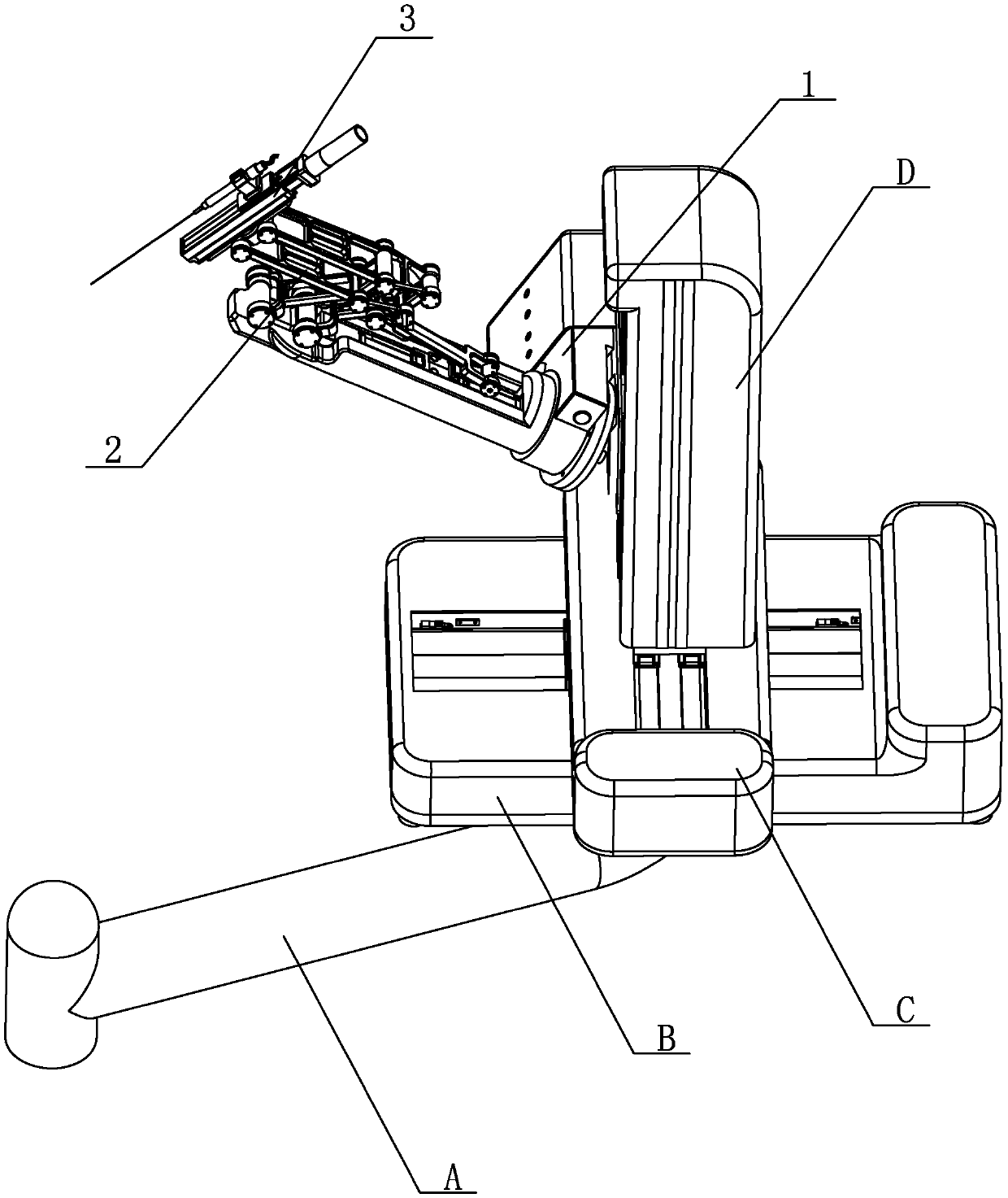
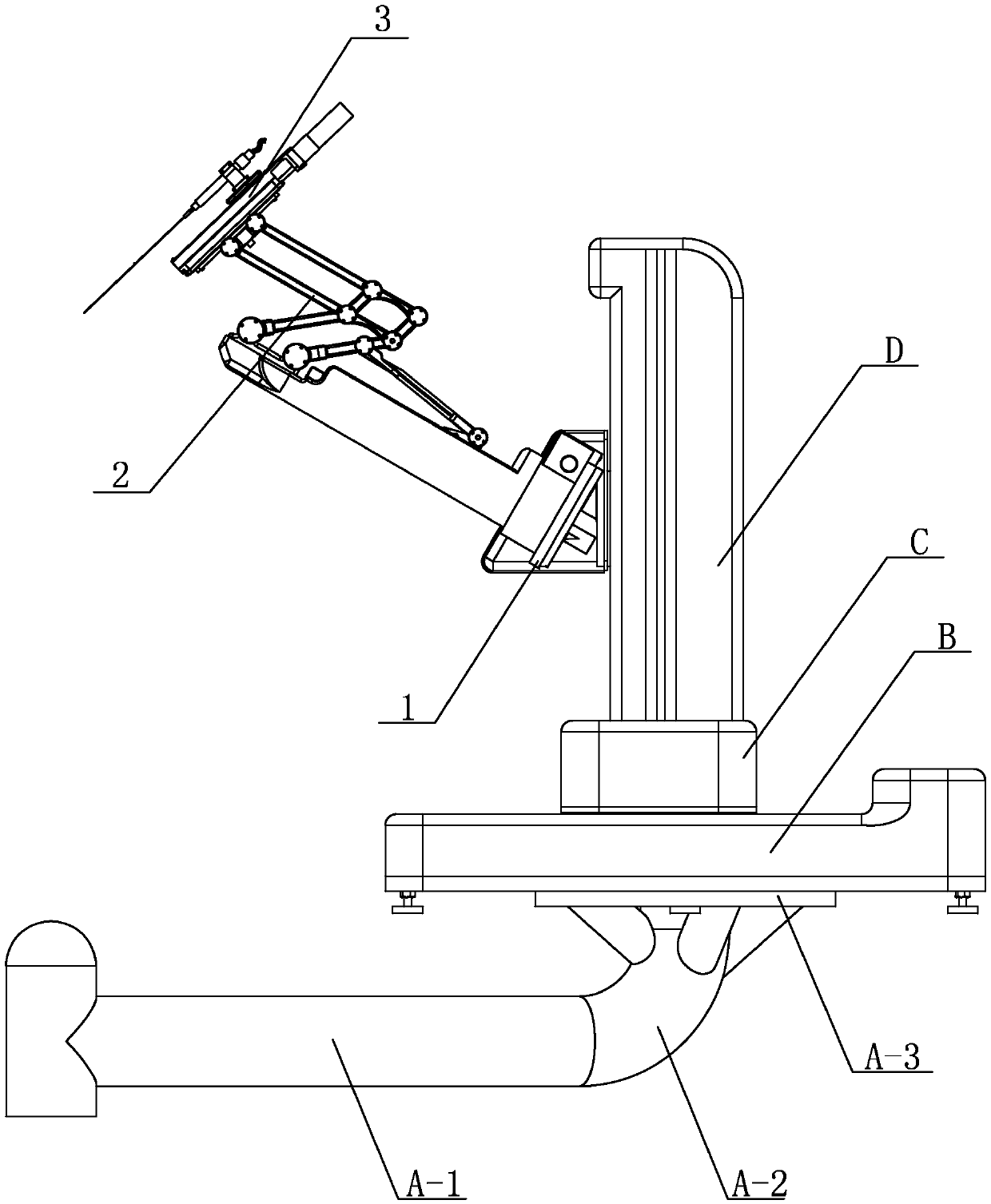
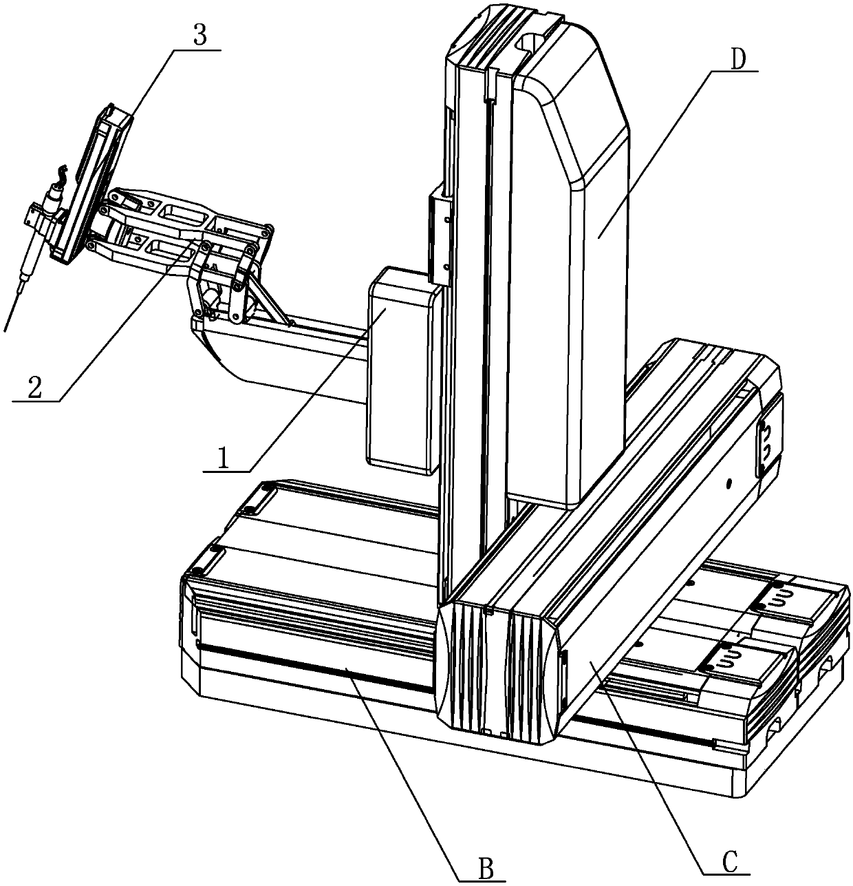
[0015] Specific implementation mode one: combine Figure 1 to Figure 5 Describe this embodiment, the robotic arm of this embodiment for microsurgery of the fundus and retina includes a cantilever rotation module 1; it also includes a link assembly 2 and an end effector assembly 3, and the cantilever rotation module 1 includes a rotation module 1- 1. Cantilever base 1-2, cantilever 1-3, cantilever linear guide module 1-4, cantilever slider 1-5, cantilever slider connector 1-6 and rotating module shell 1-7, cantilever base 1- One end of 2 is connected to an external mobile device, the other end of the cantilever base 1-2 is connected to the rotating module 1-1, the cantilever 1-3 is connected to the rotating module 1-1, and the cantilever linear guide module 1-4 is installed on the cantilever 1 In -3, the cantilever slider 1-5 is slidably installed on the cantilever linear guide rail module 1-4, the cantilever slider connector 1-6 is installed on the cantilever slider 1-5, and t...
specific Embodiment approach 2
[0024] Specific implementation mode two: combination Figure 4 Describe this embodiment, the rotating module 1-1 of this embodiment comprises motor, transmission device, worm and worm wheel, the output end of motor is connected with transmission device, the output end of transmission device is connected with worm wheel, and worm screw is installed on the cantilever 1-3 Inside, and the worm meshes with the worm gear. In actual use, the manufacturer of the rotation module 1-1 is R150M produced by Parker. Such arrangement drives the rotation of the entire cantilever 1-3 around the cantilever axis; the connection method is simple and reliable, and other components and connection relations are the same as those in the first embodiment.
specific Embodiment approach 3
[0025] Specific implementation mode three: combination figure 1 To describe this embodiment, the model of the cantilever linear guide module 1-4 in this embodiment is KK40-01P-150A-F2ES2 (PNP). With such arrangement, the stroke is large, the production is convenient, and the cost is low. Other compositions and connections are the same as those in Embodiment 1 or 2.
PUM
 Abstract
Description
Claims
Application Information