Electronic brake system and methods of operating the same

A technology of electronic braking and working method, which is applied in the direction of braking control system, ABS control system, braking action activation device, etc., which can solve the problems of reducing vehicle driving safety and the influence of braking force distribution, etc., so as to improve driving safety , load reduction, and simple structure

Active Publication Date: 2019-04-02
HL MANDO CORP
View PDF7 Cites 4 Cited by
  • Summary
  • Abstract
  • Description
  • Claims
  • Application Information

AI Technical Summary

Problems solved by technology

However, during regenerative braking, the distribution of the braking force applied to the multiple wheels of the vehicle is affected, causing oversteering, understeering, or skidding of the vehicle, which may reduce the driving safety of the vehicle. question

Method used


Image

  • Electronic brake system and methods of operating the same
  • Electronic brake system and methods of operating the same
  • Electronic brake system and methods of operating the same

Examples


Embodiment Construction

[0072] Hereinafter, embodiments of the present invention will be described in detail with reference to the drawings. The embodiments described below are disclosed in order to fully convey the idea of ​​the present invention to those skilled in the art to which the present invention pertains. The present invention is not limited to the embodiments disclosed below, but can also be implemented in other ways. In order to clearly explain the present invention, the drawings omit the illustration of parts irrelevant to the description, and in the drawings, the width, length, thickness, etc. of the constituent elements are sometimes enlarged for convenience of explanation. Throughout the specification, the same reference numerals denote the same constituent elements.

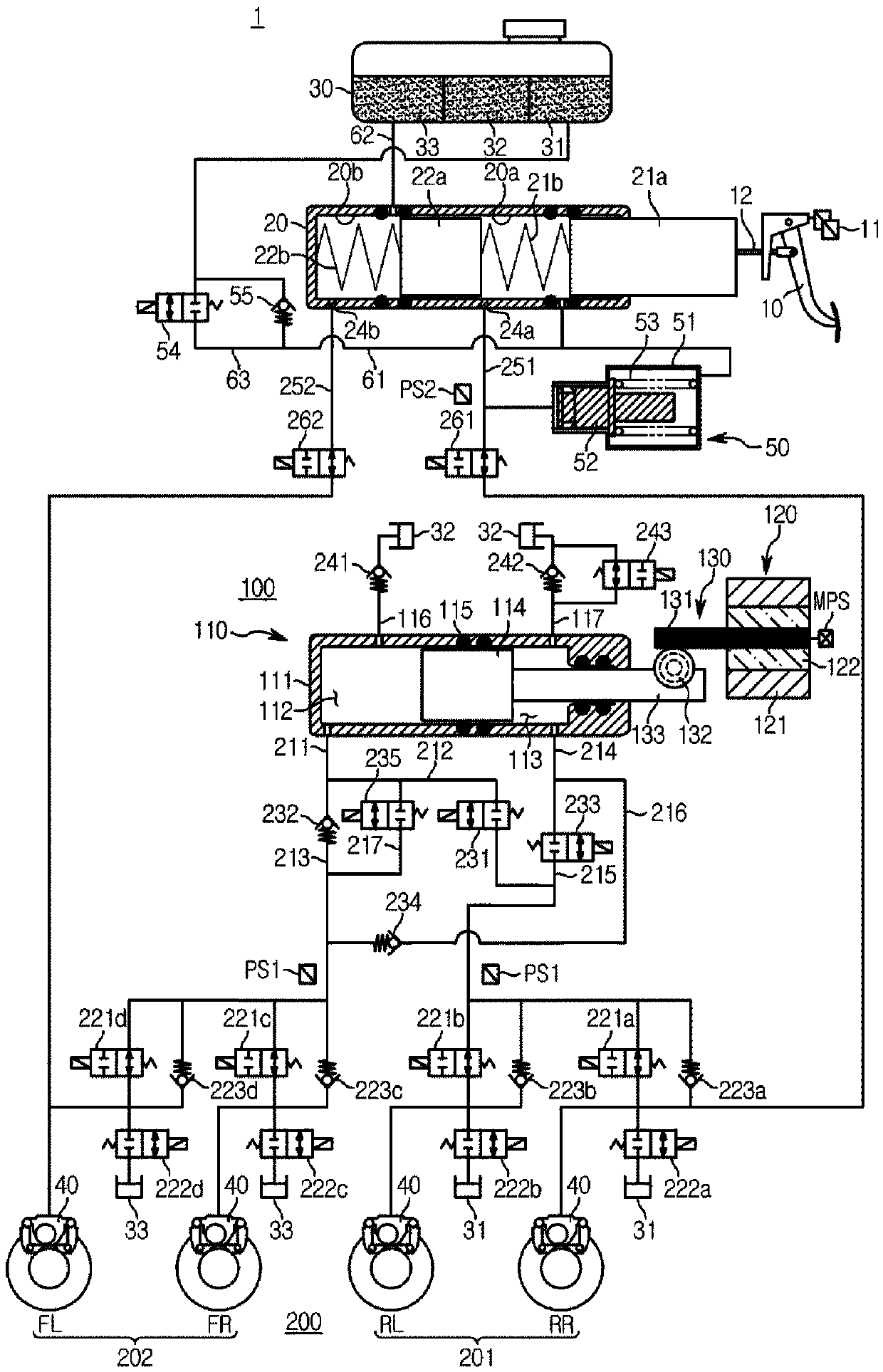
[0073] figure 1 is a hydraulic circuit diagram showing the non-operating state of the electronic brake system according to the embodiment of the present invention.

[0074] Referring to the drawings, in general, an e...


PUM


Abstract

Provided are an electric brake system and an operating method thereof. The electric brake system includes a master cylinder to discharge a pressurized medium in accordance with displacement of a brakepedal, a simulation device to provide a driver with a pedal feeling, a hydraulic pressure supply device to generate a hydraulic pressure by operating a hydraulic piston in accordance with an electrical signal output in response to the displacement of the brake pedal, and a hydraulic control unit to control a hydraulic pressure of the pressurized medium supplied to each wheel cylinder. The electric brake system may perform a normal mode, an abnormal mode, and an inspection mode.

Description

technical field [0001] The present invention relates to an electronic braking system and a working method, in more detail, an electronic braking system and a working method for generating braking force by using an electrical signal corresponding to the displacement of a brake pedal. Background technique [0002] A braking system for performing braking is always installed in a vehicle, and various types of braking systems have been proposed for the safety of drivers and passengers. [0003] Existing braking systems mainly use a method in which hydraulic pressure required for braking is supplied to the wheel cylinders by using a mechanically connected booster when the driver depresses the brake pedal. However, as the market demand for implementing various braking functions by carefully responding to the driving environment of the vehicle has increased, recently, there has been an electric signal from a pedal displacement sensor that detects the displacement of the brake pedal ...

Claims


Application Information

Patent Timeline
Patent Type & Authority Applications(China)
IPC IPC(8): B60T13/66B60T13/74B60T8/40B60T7/04
CPCB60T7/042B60T8/4081B60T13/662B60T13/745B60T2270/404B60T8/4018B60T8/4063B60T8/90B60T13/686B60T8/36B60T8/4086B60T13/142B60Y2400/81B60T8/17B60T8/341B60T8/409B60T13/165B60T13/58B60T15/028B60T17/221B60T2270/10B60T2270/402B60T2270/406B60T2270/82
Inventor 郑孝镇崔成镐
Owner HL MANDO CORP
Why Eureka
Try Eureka