
Concrete gravity dam foundation drainage hole structure and construction method thereof

A technology of gravity dams and drainage holes, which is applied in infrastructure engineering, gravity dams, dams, etc., can solve the problems of not having too much space to arrange corridors, unfavorable stability of dams, poor drainage effect, etc., and achieve significant drainage effect and optimization. The effect of the dam body shape and the reduction of the engineering quantity

Pending Publication Date: 2019-04-02
POWERCHINA HUADONG ENG COPORATION LTD
View PDF3 Cites 2 Cited by
  • Summary
  • Abstract
  • Description
  • Claims
  • Application Information

AI Technical Summary

Problems solved by technology

When the drainage hole adopts self-flow drainage, a large water pressure will be formed in the drainage hole, and the drainage effect will be poor, resulting in a large uplift pressure at this part, and the seepage pressure intensity coefficient even exceeds the limit value specified in the code, which is not good for the stability of the dam.
In order to solve this problem, it is necessary to adjust the layout of the corridors, such as adding horizontally arranged corridors and connecting them with the main corridor through bypass corridors, or setting up corridors in layers and connecting them through shafts, but this arrangement is obviously not conducive to construction , especially for roller compacted concrete gravity dams, and some projects do not have much space to arrange corridors due to other structural layout requirements

Method used


Image

  • Concrete gravity dam foundation drainage hole structure and construction method thereof
  • Concrete gravity dam foundation drainage hole structure and construction method thereof
  • Concrete gravity dam foundation drainage hole structure and construction method thereof

Examples


Embodiment Construction

[0028] The present invention will be further described below in conjunction with the accompanying drawings and specific embodiments.

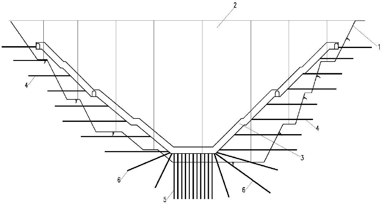
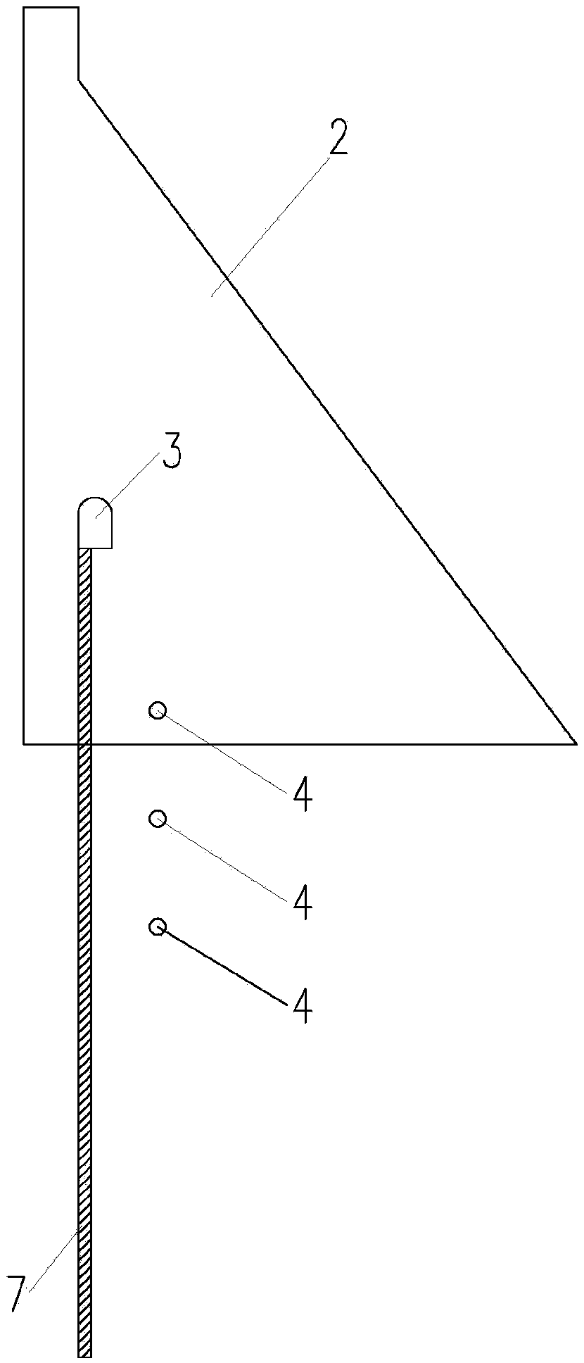
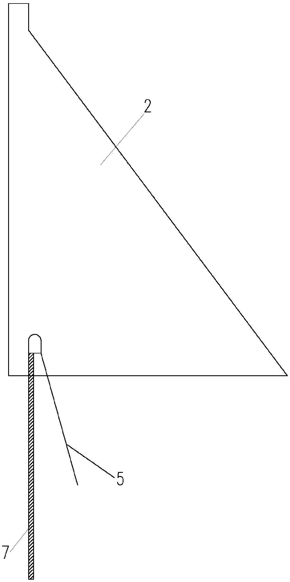
[0029] Such as figure 1 , figure 2 , image 3 , Figure 4 As shown, a concrete gravity dam 2 dam foundation drainage hole structure of the present invention includes a dam foundation 1 and a gravity dam 2, a corridor 3 is arranged in the gravity dam 2, and a curtain 7 is grouted at the upstream of the corridor 3 in the gravity dam 2 , the corridor 3 includes a slope section and a horizontal section at the bottom of the riverbed, the slope section of the corridor 3 is provided with a horizontal drainage hole 4, the horizontal section at the bottom of the riverbed of the corridor 3 is provided with a vertical drainage hole 5, and the slope section of the corridor 3 and the bottom of the riverbed Slanted drainage holes 6 are provided at the junction between the horizontal sections.

[0030] The height difference of the horizontal drainage hol...


PUM


Abstract

The invention discloses a concrete gravity dam foundation drainage hole structure and a construction method thereof. The concrete gravity dam foundation drainage hole structure and the construction method thereof have the advantages that: impacts of gallery layout to drainage effects are lowered, a drainage ability of a dam foundation is improved, uplift pressure of the dam foundation is lowered,and when an uplift pressure monitoring device is in a damaged or repaired duration, a temporary observing function is also obtained. The concrete gravity dam foundation drainage hole structure comprises the dam foundation and a gravity dam, a gallery is arranged inside the gravity dam, curtain grouting is arranged on the upstream of the gallery through the gravity dam, the gallery comprises a slope section and a riverbed bottom horizontal section, horizontal drainage holes are arranged on the slope section of the gallery, vertical drainage holes are arranged on the riverbed bottom of the gallery, and inclined drainage holes are formed in the combination part of the slope section and the riverbed bottom horizontal section of the gallery.

Description

technical field [0001] The invention relates to a concrete gravity dam foundation drainage hole arranged based on the seepage characteristics of the dam foundation and a construction method thereof. It is suitable for temporary monitoring of drainage and uplift pressure of concrete gravity dam foundations, especially for concrete gravity dam projects with high and steep bank slopes. Background technique [0002] The uplift pressure of the concrete gravity dam foundation is one of the important factors affecting the stability and stress of the dam, especially for the bank slope dam section, the uplift pressure has a great influence on the lateral stability of the dam. Therefore, effectively reducing the uplift pressure of the dam foundation can improve the stability of the dam under the premise of ensuring the anti-seepage effect. At present, the upstream of the concrete gravity dam adopts curtain grouting for anti-seepage treatment. In order to further reduce the uplift pre...

Claims


Application Information

Patent Timeline
IPC IPC(8): E02D27/40E02B7/10E02D19/06
CPCE02B7/10E02D19/06E02D27/40
Inventor 朱安龙张弦张胜利
Owner POWERCHINA HUADONG ENG COPORATION LTD
Learn More