Full-automatic storage tank
A safe deposit box, fully automatic technology, applied in safe boxes, conveyor objects, manipulators, etc., can solve problems such as low efficiency, easy exposure of personal privacy, insecurity, etc., to achieve smooth transportation, improve site adaptability, and small footprint Effect
- Summary
- Abstract
- Description
- Claims
- Application Information
AI Technical Summary
Problems solved by technology
Method used
Image
Examples
Embodiment 1
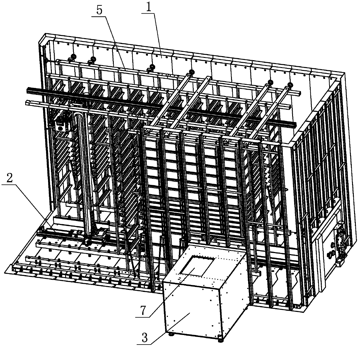
[0046] Embodiment one: if figure 1 As shown, a fully automatic safe deposit box includes a warehouse body 1, a handling robot 2 is arranged inside the warehouse body 1, and at least one viewing platform is arranged outside the warehouse body 1, and the viewing platform includes a protective shell 3 outside the warehouse and a conveying device 4 , the two sides of the handling robot 2 are provided with box storage racks 5 for storing storage boxes, and the conveying device 4 is arranged between the outer protective shell 3 and the warehouse body 1, and the top of the outer protective shell 3 is provided with a storage box access port 7; when taking out the box, the handling robot 2 will extract the corresponding storage box from the storage rack 5 and transport it to the conveying device 4, and the conveying device 4 will send the storage box into the outer protective shell 3 and Transport to the access port 7. When storing the box, the delivery device 4 sends the storage box f...
Embodiment 2
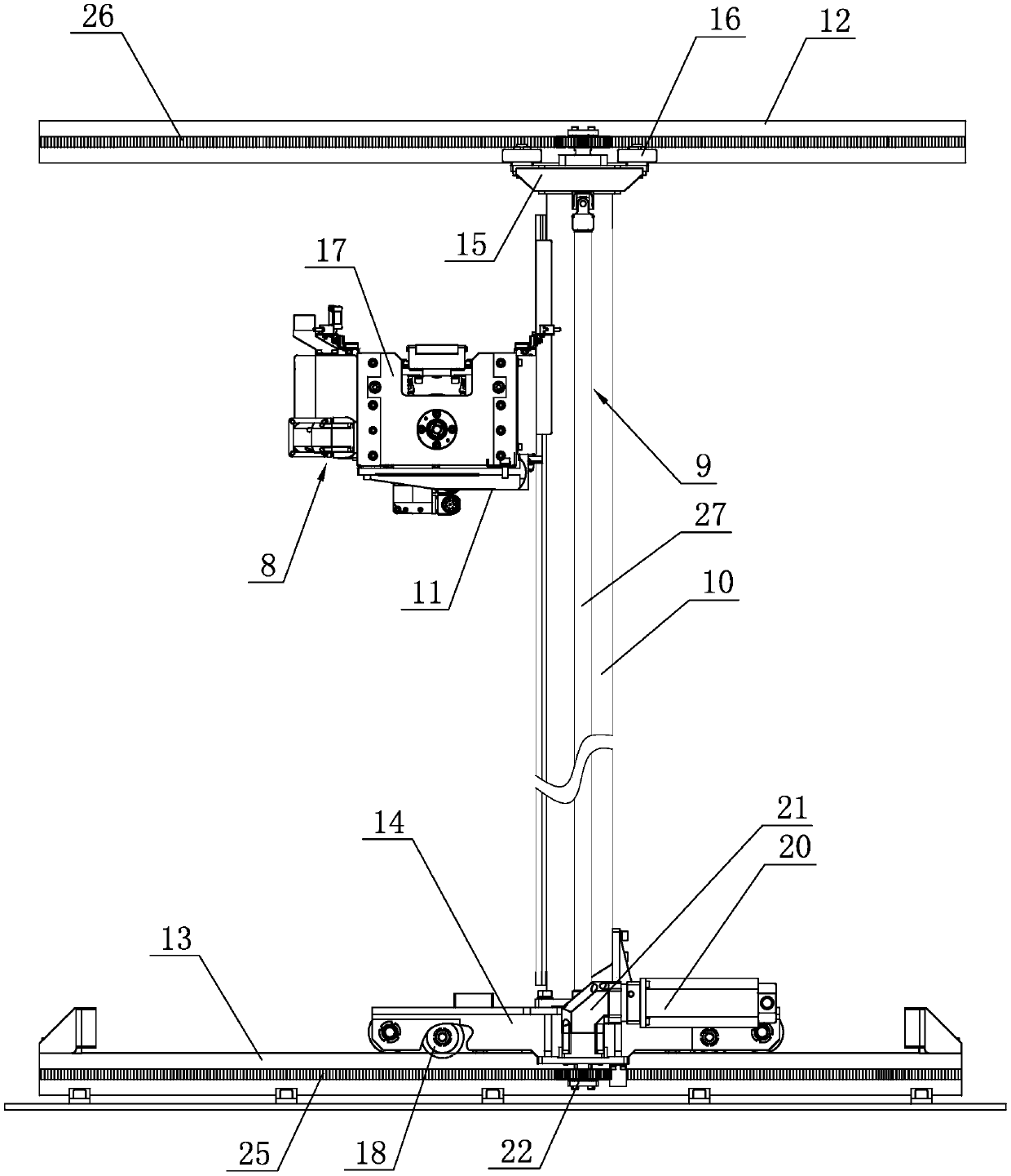
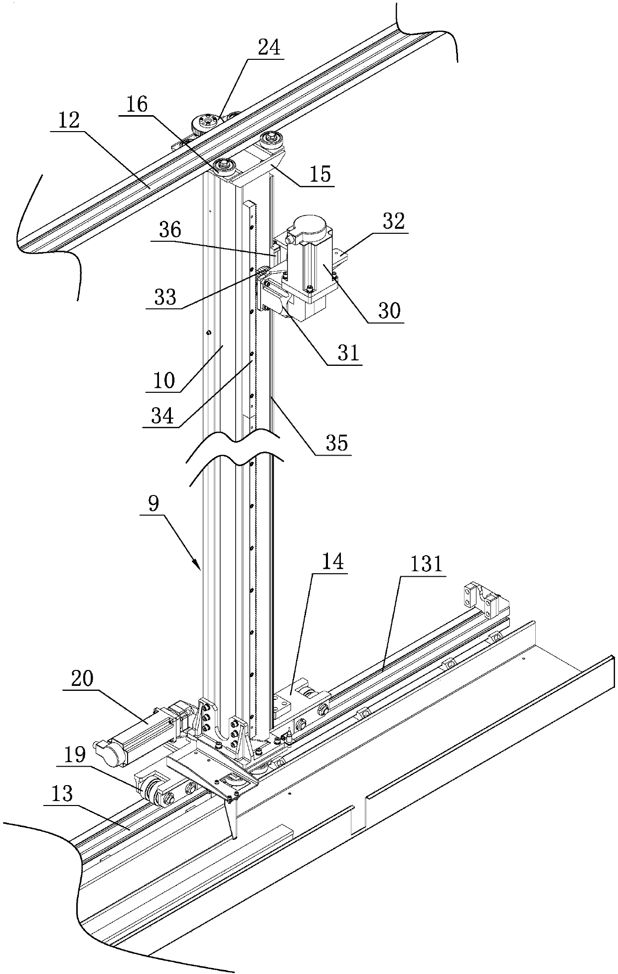
[0047] Embodiment two: other structures are identical with embodiment one, and its difference is: as Figure 2-Figure 4As shown, the handling robot 2 includes an extracting device 8, a lifting device 9 and a lateral walking device for driving the lifting device 9 to reciprocate horizontally and horizontally. The device includes a sky rail 12, a ground rail 13, a top travel assembly, a bottom travel assembly, a synchronous transmission assembly and a travel drive assembly. The bottom travel assembly includes a bottom mounting seat 14 and a ground rail rolling assembly, and the bottom mounting seat 14 slides through the ground rail rolling assembly. Set on the ground rail 13, the bottom mounting base 14 is fixedly connected to the lower end of the column 10, and a ground rail clamping assembly that can roll along the ground rail 13 is also provided between the bottom mounting base 14 and the ground rail 13; the top walking assembly includes a top The mounting base 15 and a plura...
Embodiment 3
[0052] Embodiment three, other structures are identical with embodiment two, and its difference is: as Figure 6-Figure 10 As shown, the extraction conveying mechanism includes an extracting mechanism and a horizontal conveying mechanism. The extracting mechanism includes a front handle assembly 37, a rear handle assembly 38, a sliding wheel 39, and a handle switching mechanism for driving the sliding wheel 39 to rotate in a pendulum manner. The sliding wheel A front handle assembly 37 is fixed on the front side of the 39, and a rear handle assembly 38 is fixed on the rear side of the sliding runner 39. The front handle assembly 37 and the rear handle assembly 38 are arranged symmetrically with the central axis of the sliding runner 39,
[0053] The front handle assembly 37 has the same structure as the rear handle assembly 38. The front handle assembly 37 includes a handle 371, a handle mounting plate 372, a connecting rod 373 and a connecting rod connecting block 374. The han...
PUM
 Abstract
Description
Claims
Application Information
 - R&D Engineer
- R&D Manager
- IP Professional
- Industry Leading Data Capabilities
- Powerful AI technology
- Patent DNA Extraction
Browse by: Latest US Patents, China's latest patents, Technical Efficacy Thesaurus, Application Domain, Technology Topic, Popular Technical Reports.
© 2024 PatSnap. All rights reserved.Legal|Privacy policy|Modern Slavery Act Transparency Statement|Sitemap|About US| Contact US: help@patsnap.com


