A micro-free piston power device with a self-pressurized direct-flow scavenging structure

A piston-powered, self-pressurized technology, applied in the field of micro-power systems, can solve problems such as excessive residual exhaust gas, poor ventilation quality, short-circuit overflow of scavenging, and achieve the effect of enhancing the scavenging effect

Active Publication Date: 2020-12-18
JIANGSU UNIV
View PDF3 Cites 0 Cited by
  • Summary
  • Abstract
  • Description
  • Claims
  • Application Information

AI Technical Summary

Problems solved by technology

However, the research on the micro-free piston power device is still in the early stage of discussion, and its device also has some shortcomings: the structure distribution is relatively compact, and the scavenging time of the two-stroke is shorter than that of the four-stroke, and the scavenging system has not been effectively improved, which is prone to short scavenging Road overflow, poor ventilation quality, and more residual exhaust gas, resulting in reduced output power

Method used


Image

  • A micro-free piston power device with a self-pressurized direct-flow scavenging structure
  • A micro-free piston power device with a self-pressurized direct-flow scavenging structure
  • A micro-free piston power device with a self-pressurized direct-flow scavenging structure

Examples


Embodiment Construction

[0021] In order to make the object, technical solution and advantages of the present invention more clear, the present invention will be further described in detail below in conjunction with the accompanying drawings and embodiments. It should be understood that the specific embodiments described here are only used to explain the present invention, not to limit the present invention.

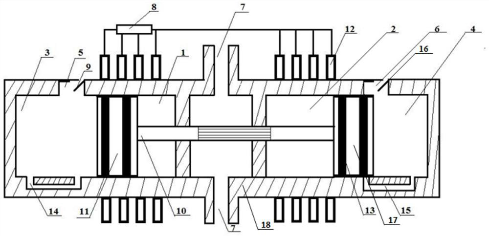
[0022] Such as figure 1 As shown, the present invention proposes a micro-free piston power device with a self-pressurized DC scavenging structure, including a cylinder 18, a stator winding 12 and a rectifier 8, the stator winding 12 is wound on the outer surface of the cylinder 18, and the rectifier 8 passes through the The wires are connected to the stator winding 12; from left to right, a first cavity, an exhaust chamber, and a second cavity are arranged in the cylinder 18, and the exhaust chamber is arranged between the first cavity and the second cavity, and the exhaust chamber is arranged b...


PUM


Abstract

The invention discloses a micro-free piston power unit with a self-pressurized type uniflow scavenging structure. The micro-free piston power unit comprises a gas cylinder, a stator winding and a rectifier, the stator winding is wound around the outer surface of the gas cylinder, and the rectifier is connected with the stator winding; the gas cylinder is internally provided with two cavities and an exhaust chamber, the exhaust chamber is formed between the two cavities, partition plates are arranged between the two ends of the exhaust chamber and the two cavities, and the exhaust chamber is provided with an exhaust opening; the two cavities are symmetrically distributed through the center axis of the exhaust opening, a gas inlet is formed in the upper end of each cavity, and a self-pressurized gas inlet channel is formed in the inner bottom of each cavity; and two magnetic pistons are located in the two cavities correspondingly, thus the cavities are internally divided into scavengingchambers and combustion chambers, a piston connecting rod penetrates through the partition plates to connect the two magnetic pistons, and the piston connecting rod is provided with an axial groove structure. According to the self-pressurized type uniflow scavenging structure, the structure design is simple, the gas inlet pressure is increased through the self operation process, meanwhile, the position of a waste gas outlet is changed to form the uniflow scavenging mode, and the scavenging effect of the micro power unit is improved advantageously.

Description

technical field [0001] The invention belongs to the micro power system related to the field of internal combustion engine and the field of power generation, in particular to a micro free piston power device equipped with a self-pressurized direct current scavenging structure. Background technique [0002] In the field of energy and power, improving energy utilization has always been one of the important topics. Researchers from various countries are developing new energy conversion devices. Among them, the power device formed by the combination of a free piston internal combustion engine and a linear generator, compared with traditional engines, Because it does not require a crank-link mechanism, it has the advantages of simple structure, high energy density, and wide fuel applicability. It has become one of the typical new energy conversion devices. When the device is running, the free piston compresses the homogeneous gas. After the combustion gas is compressed and ignited,...

Claims


Application Information

Patent Timeline
Patent Type & Authority Patents(China)
IPC IPC(8): F02B63/04F02B75/24F02B25/02F02B33/06F02F3/00H02K7/18
CPCF02B25/02F02B33/06F02B63/041F02B75/24F02B2075/1808F02F3/0084H02K7/1884Y02T10/12
Inventor 柏金王谦黄蓉
Owner JIANGSU UNIV
Why Eureka
Try Eureka