Collimating lens and projection module

A lens and collimation technology, which is applied in the field of camera lenses, can solve problems such as enlarged image points, low yield, and affecting the accuracy of three-dimensional object outline restoration, achieving the effect of stable focal length and low cost

Active Publication Date: 2019-04-02
JIANGXI LIANYI OPTICS CO LTD
View PDF8 Cites 18 Cited by
  • Summary
  • Abstract
  • Description
  • Claims
  • Application Information

AI Technical Summary

Problems solved by technology

[0004] However, in the existing smartphones, as the temperature of the use environment changes, the focal length f of the lens changes greatly, resulting in a significant change in the angle of the lens projected light, which will change the original light information, resulting in the entire There are errors in the calculation of the system, which affect the accuracy of the contour restoration of the three-dimensional object. There is also the case that the projected image point becomes larger with the change of temperature, which will also lead to a decrease in the definition of the three-dimensional object restored by the system. Therefore, with the use of When the ambient temperature changes, it is particularly important that the field of view angle and the size of the spot of the light information projected to the measured object do not change greatly
[0005] In addition, the first lens of the traditional collimator lens close to the laser transmitter is a molded glass lens. This molded glass lens is too small, difficult to produce and process, low yield, and difficult to mass-produce, which greatly increases the production cost.

Method used


Image

  • Collimating lens and projection module
  • Collimating lens and projection module
  • Collimating lens and projection module

Examples


no. 1 example

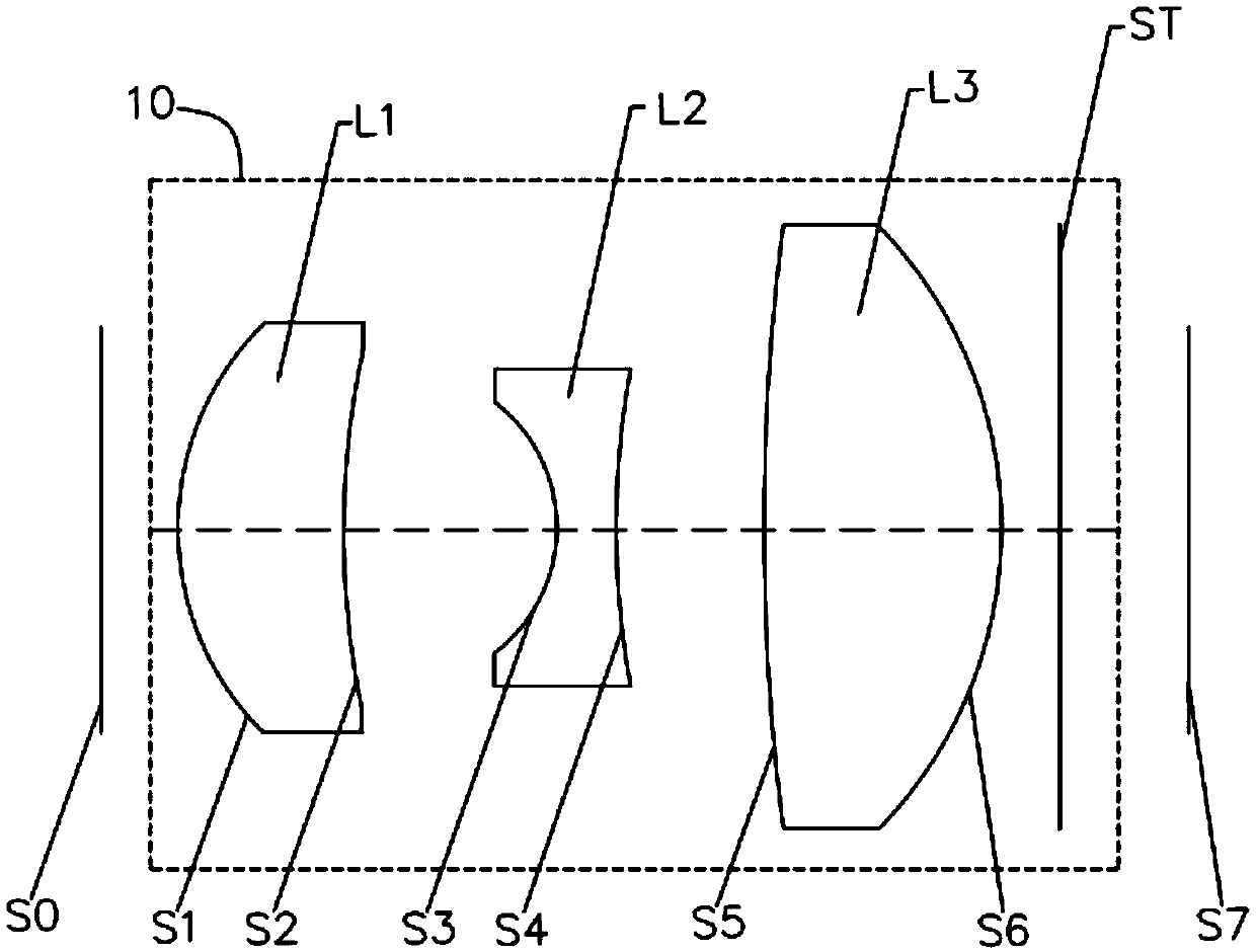
[0087] see figure 1 , a schematic structural diagram of a collimator lens 10 provided in this embodiment, the laser emitter end is set as the object side S0, the measured object end is the image side S7, and the sequence from the object side S0 to the image side S7 includes: the first lens L1, second lens L2, third lens L3 and stop ST.

[0088] The first lens L1 has positive refractive power, the object side S1 of the first lens L1 is a convex surface, and the image side S2 of the first lens L1 is a concave surface.

[0089] The second lens L2 has negative refractive power, and both the object side S3 and the image side S4 of the second lens L2 are concave.

[0090] The third lens L3 has positive refractive power, the object side S5 of the third lens L3 is concave and the image side S6 is convex.

[0091] The stop ST is located between the third lens L3 and the object to be measured. The optical centers of each lens are located on the same straight line, and each lens is ma...

no. 2 example

[0105] The structural representation of the collimating lens 20 of the present embodiment can refer to Figure 5 . This embodiment is roughly similar to the lens structure diagram of the first embodiment, except that the relevant parameters of each lens are different.

[0106] The relevant parameters of each lens in the collimating lens 20 in this embodiment are shown in Table 3.

[0107] table 3

[0108] Surface serial number

surface type

r

d

n d

Vd

object plane S0

sphere

0.420

S1

first lens

Aspherical

0.646

0.395

1.640

23.529

S2

Aspherical

1.289

0.823

S3

second lens

Aspherical

-0.513

0.266

1.516

57.038

S4

Aspherical

14.889

0.657

S5

third lens

Aspherical

5.288

0.525

1.640

23.529

S6

Aspherical

-1.233

0.350

ST

aperture

sphere

300.000...

no. 3 example

[0115] The structural representation of the collimating lens 30 of the present embodiment can refer to Figure 9 , this embodiment is roughly similar to the lens structure diagram of the first embodiment, except that the relevant parameters of each lens are different.

[0116] The relevant parameters of each lens in the collimating lens 30 in this embodiment are shown in Table 5.

[0117] table 5

[0118] Surface serial number

surface type

r

d

n d

Vd

object plane S0

sphere

0.250

S1

first lens

Aspherical

0.647

0.524

1.640

23.529

S2

Aspherical

1.412

0.592

S3

second lens

Aspherical

-0.726

0.170

1.640

23.529

S4

Aspherical

1.232

0.773

S5

third lens

Aspherical

21.774

0.641

1.640

23.529

S6

Aspherical

-1.054

0.400

ST

aperture

sphere

300.000 ...


PUM

PropertyMeasurementUnit
optical path lengthaaaaaaaaaa

Abstract

The invention provides a collimating lens and a projection module. A laser emitter side is set as an object side and a measured object end is set as an image side. A first lens having the positive focal power, a second lens having the negative focal power, a third lens having the positive focal power, and a diaphragm are arranged successively along the optical axis from the object side to the image side. The object side surface of the first lens is a convex surface; the object side surface of the second lens is a concave surface; the object side surface of the third lens is a convex surface ora near plane and the image side surface is a convex surface. The diaphragm is arranged between the third lens and a measured object. The first lens, the second lens and the third lens are all made ofplastic materials. The collimating lens meets the following conditional expression: (dn / dt) 1 is less than -30*10<-6> / DEG C, (dn / dt) 2 is less than -30*10<-6> / DEG C, and (dn / dt)3 is less than -30*10<-6> / DEG C. According to the invention, the changing rates of refractive indexes of the three lenses with the temperature are defined clearly and thus reasonable matching of the thermal expansion characteristics of the lenses is realized, so that the stable focal length is realized. The collimating lens and the projection module are suitable for different temperature applications.

Description

technical field [0001] The invention relates to the field of camera lens technology, in particular to a collimator lens and a projection module. Background technique [0002] With the rapid development of smart phones, innovative technologies are constantly emerging in the camera functions of mobile phones, such as the 3D imaging technology promoted by Apple, which is an optical sensing technology based on 3D structured light, which can be used for face and gesture recognition, enhanced The camera function brings new AR applications, transforming optical images from the past two-dimensional space to three-dimensional space, thus bringing a more real and clear perception experience. [0003] 3D structured light means that after specific laser information is projected onto the surface of an object, it is collected by a camera, and information such as the position and depth of the object is calculated according to the change of light information caused by the object, and then t...

Claims


Application Information

Patent Timeline
Patent Type & Authority Applications(China)
IPC IPC(8): G02B19/00G03B15/02G02B1/04
CPCG02B19/0014G02B19/0047G03B15/02G02B1/041G02B13/0035G02B7/008H04M1/0264H04M2250/52G01B11/2513G01B5/0014H04N23/55G02B13/0055G02B27/30H04N9/3161
Inventor 刘绪明曾昊杰曾吉勇
Owner JIANGXI LIANYI OPTICS CO LTD
Why Eureka
Try Eureka