Flat copper wire formed stator coil high-reluctance torque outer rotor type permanent magnet drive motor

A stator coil and permanent magnet drive technology, which is applied to the rotating parts of the magnetic circuit, the shape/style/structure of the magnetic circuit, the shape/style/structure of the winding conductor, etc., can solve the inconvenient operation of the robot and the irreversible demagnetization of the permanent magnet , low energy conversion rate and other issues, to achieve the effect of large reluctance torque, small water resistance and good cost performance

Pending Publication Date: 2019-04-02
宁德时代电机科技有限公司
View PDF0 Cites 3 Cited by
  • Summary
  • Abstract
  • Description
  • Claims
  • Application Information

AI Technical Summary

Problems solved by technology

However, the permanent magnet is installed on the rotor, and it is difficult to dissipate heat. The temperature rise caused may cause irreversible demagnetization of the permanent magnet, which limits the output of the motor and increases the potential safety hazard.
[0003] At present, the stator core of the permanent magnet motor is closed slotted, which is inconvenient for the robot to operate; the magnetic steel is arranged in a straight line, and the energy conversion rate is low, and the rotor punching plate adopts the entire ring structure, which wastes a lot of materials

Method used


Image

  • Flat copper wire formed stator coil high-reluctance torque outer rotor type permanent magnet drive motor
  • Flat copper wire formed stator coil high-reluctance torque outer rotor type permanent magnet drive motor
  • Flat copper wire formed stator coil high-reluctance torque outer rotor type permanent magnet drive motor

Examples


Embodiment

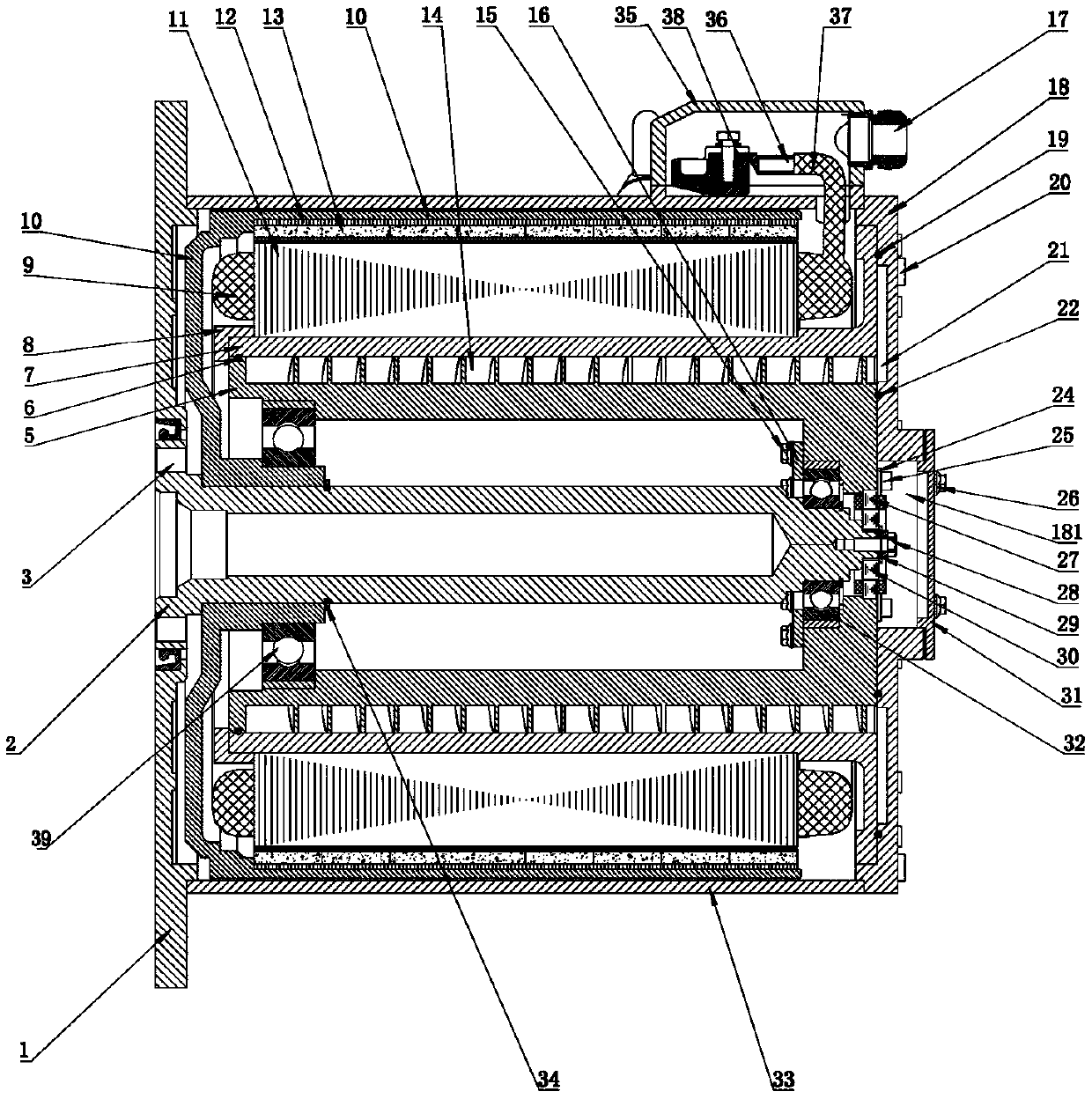
[0026] A flat copper wire formed stator coil high reluctance torque outer rotor permanent magnet drive motor, such as Figure 1-Figure 7As shown, it includes a coupling shaft 2, and the left and right sides of the coupling shaft 2 are respectively connected with a front end cover 1 and a double spiral waterway ring 5 through a front bearing 3 and a rear bearing 32; The fixed retaining ring 16 is arranged on the double-helix waterway ring 5, and the fixed retaining ring 16 of the rear bearing is fixed on the double-helix waterway ring 5 by the rear bearing retaining ring fixing screw 17; the outer ring of the double-helix waterway ring 5 is connected to There is a waterway outer ring 7 matched with the double helix waterway ring 5, and the double helix waterway ring 5 cooperates with the waterway outer ring 7 to form a double helix waterway 14; the outer side of the double helix waterway ring 5 is provided with a stator waterway rear end cover 18 The rear end cover 18 of the st...


PUM


Abstract

The invention discloses a flat copper wire formed stator coil high-reluctance torque outer rotor type permanent magnet drive motor. The permanent magnet drive motor comprises a coupler shaft, whereinthe left and right sides of the coupler shaft are connected with a front end cover and a double-screw water channel ring respectively; a rear bearing is fixed onto the double-screw water channel ring;the double-screw water channel ring is matched with a water channel outer ring to form a double-screw water channel; the water channel outer ring is connected with an inner stator iron core; the coupler shaft is provided with an outer rotor magnet yoke fixed barrel; a self-buckle type outer rotor iron core is arranged on the inner surface of the outer rotor magnet yoke fixed barrel; and a plurality of magnetic steel is arranged on the self-buckle type outer rotor iron core in an inserted manner. By using the distribution of inverted V-shaped magnetic steel, the permanent magnet drive motor has the characteristic of high reluctance torque; a flat copper formed coil is used, a stator is an open slot, and the utilization rate of the slot is improved by 25% compared with that of a circular copper wire; a machine hand can be used for inserting winding; the efficiency of the motor can be improved by using more copper and few magnetic steel, the cost is reduced, the power density and torquedensity are improved, and the cost performance is higher; and the double-screw water channel has the advantages of low water resistance and high heat dissipation capacity.

Description

technical field [0001] The invention relates to the field of energy equipment, in particular to a flat copper wire formed stator coil high reluctance torque outer rotor permanent magnet drive motor. Background technique [0002] Permanent magnet motors have the advantages of high efficiency, high power density, large power factor, large starting torque, wide speed range, etc., and have gradually replaced induction motors and switched reluctance motors, and are increasingly being used in many fields of industrial production and daily life. Wide range of applications. However, since the permanent magnet is installed on the rotor, it is difficult to dissipate heat. The temperature rise caused by the permanent magnet may cause irreversible demagnetization of the permanent magnet, which limits the output of the motor and increases the potential safety hazard. [0003] At present, the stator core of the permanent magnet motor is closed slotted, which is inconvenient for the robot...

Claims


Application Information

Patent Timeline
Patent Type & Authority Applications(China)
IPC IPC(8): H02K1/16H02K1/27H02K3/12H02K5/20H02K9/19
CPCH02K1/165H02K1/2786H02K3/12H02K5/20H02K9/19
Inventor 梁泊山孙玉凤
Owner 宁德时代电机科技有限公司
Why Eureka
Try Eureka