Feed mixing device

A mixing device and feed technology, which is applied to feed, mixers, mixers with rotating stirring devices, etc., can solve problems such as uneven mixing, and achieve the effects of improving efficiency and uniformity, avoiding unevenness, and avoiding sticking

Inactive Publication Date: 2019-04-05
陆左琴
View PDF0 Cites 0 Cited by
  • Summary
  • Abstract
  • Description
  • Claims
  • Application Information

AI Technical Summary

Problems solved by technology

[0003] The purpose of the present invention is to provide a feed mixing device for the feed mixing device in the prior art, which has the problem of uneven mixing when mixing feed.

Method used


Image

  • Feed mixing device

Examples


Embodiment Construction

[0014] The present invention will be further described below in conjunction with specific embodiment:

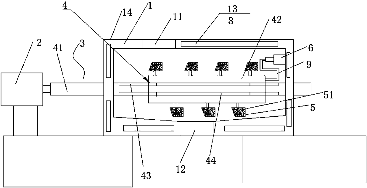
[0015] Such as figure 1 As shown, a feed mixing device includes a cylinder body 1, a driving device 2, a stirring device 3 and a heating device 8. The upper side of the cylinder body 1 is provided with a feed inlet 11, and the lower side of the cylinder body 1 is provided with a discharge port. 12. The stirring device 3 includes a stirring shaft 4, and the stirring shaft 4 includes a rotating rod 41. The rotating rod 41 runs through the middle of the cylinder 1. The two ends of the rotating rod 41 are respectively connected to the side wall of the cylinder 1 by bearings. One end of the drive device 2 is connected to the output end of the driving device 2, and the sleeve rod 42 is sleeved on the rotating rod 41, and the sleeve rod 42 is slidingly connected with the rotating rod 41. An electric cylinder 6 is arranged on the side wall of the cylinder body 1, and the electric cy...


PUM


Abstract

The invention provides a feed mixing device which comprises a barrel, a driving device, a stirring device and a heating device. A feeding port and a discharging port are arranged on the upper side andthe lower side of the barrel respectively, the stirring device comprises a stirring shaft which comprises a rotating rod, the rotating rod penetrates the middle of the barrel, two ends of the rotating rod are rotatably connected with the side wall of the barrel by bearings respectively, one end of the rotating rod is connected with the output end of the driving device, a sleeve rod sleeves the rotating rod and slidably connected with the same, an electric cylinder is arranged on the side wall in the barrel, a base of the electric cylinder is fixedly connected with the barrel, one end of a piston rod is connected with the sleeve rod through a connection member, a stirring paddle is arranged on the sleeve rod, and the heating device is arranged on the barrel. By the feed mixing device, stirring efficiency and uniformity are improved, feed stirring nonuniformity is avoided, and feed stirring quality is improved.

Description

technical field [0001] The invention relates to a feed mixing device. Background technique [0002] In large-scale breeding bases and feed production bases, feed mixers are used to mix various feed varieties together. The raw materials used include powder, liquid ingredients, and paste materials. If these three forms of materials are directly put into the production line, not only can they not be mixed evenly, which will affect the quality of the feed, but also these materials will adhere to the inner wall of the equipment. , or the pipes of the equipment will be blocked, or the sieve will be stuck, resulting in shutdown and production stoppage. Therefore, the general practice is to mix the powder, liquid ingredients, and paste materials evenly before the materials enter the production line. In order to ensure that the feed is fully mixed, it is necessary to ensure that the feed is dry. However, the feed mixing device in the prior art has the problem of uneven mixing when ...

Claims


Application Information

Patent Timeline
IPC IPC(8): B01F7/04B01F15/06B01F7/00A23N17/00
CPCA23N17/00A23N17/007B01F27/092B01F27/11251B01F27/70B01F35/92B01F2101/18B01F2035/99
Inventor 陆左琴
Owner 陆左琴
Why Eureka
Try Eureka