Mixing pot bottom discharge apparatus and application method thereof

A discharge device, pot bottom technology, applied in the direction of mixers, chemical instruments and methods, mixers with rotating stirring devices, etc., can solve the problem that the slurry is easy to infiltrate into the moving parts of the valve stem, the labor intensity of the operator is high, and it cannot be realized Remote control and other issues to achieve the effect of reducing slurry residue, simple structure, and light weight

Active Publication Date: 2019-04-05
HUBEI SANJIANG AEROSPACE JIANGHE CHEM TECH
View PDF7 Cites 0 Cited by
  • Summary
  • Abstract
  • Description
  • Claims
  • Application Information

AI Technical Summary

Problems solved by technology

[0004] Since the 1990s, major domestic vertical kneader manufacturers have equipped vertical kneaders with models of 1000L, 2000L, and 2400L with the bottom discharge method of the mixing pot. The structure adopted is as follows figure 2 As shown, in the process of delivery, there are very obvious design defects such as the difficulty of disassembly and cleaning due to the complex structure, the labor intensity of the operator, the easy penetration of the slurry into the moving parts of the valve stem, and the inability to realize remote control. The bottom discharge method cannot be used normally, and we have to go back to the old way of turning the mixing pot to discharge the material. As a result, the bottom discharge process of the mixing pot cannot be popularized and used in the production of composite solid propellant charges.

Method used


Image

  • Mixing pot bottom discharge apparatus and application method thereof
  • Mixing pot bottom discharge apparatus and application method thereof
  • Mixing pot bottom discharge apparatus and application method thereof

Examples


Embodiment Construction

[0031] The present invention will be further described below in conjunction with the examples, but the protection scope of the present invention is not limited to the scope expressed in the examples.

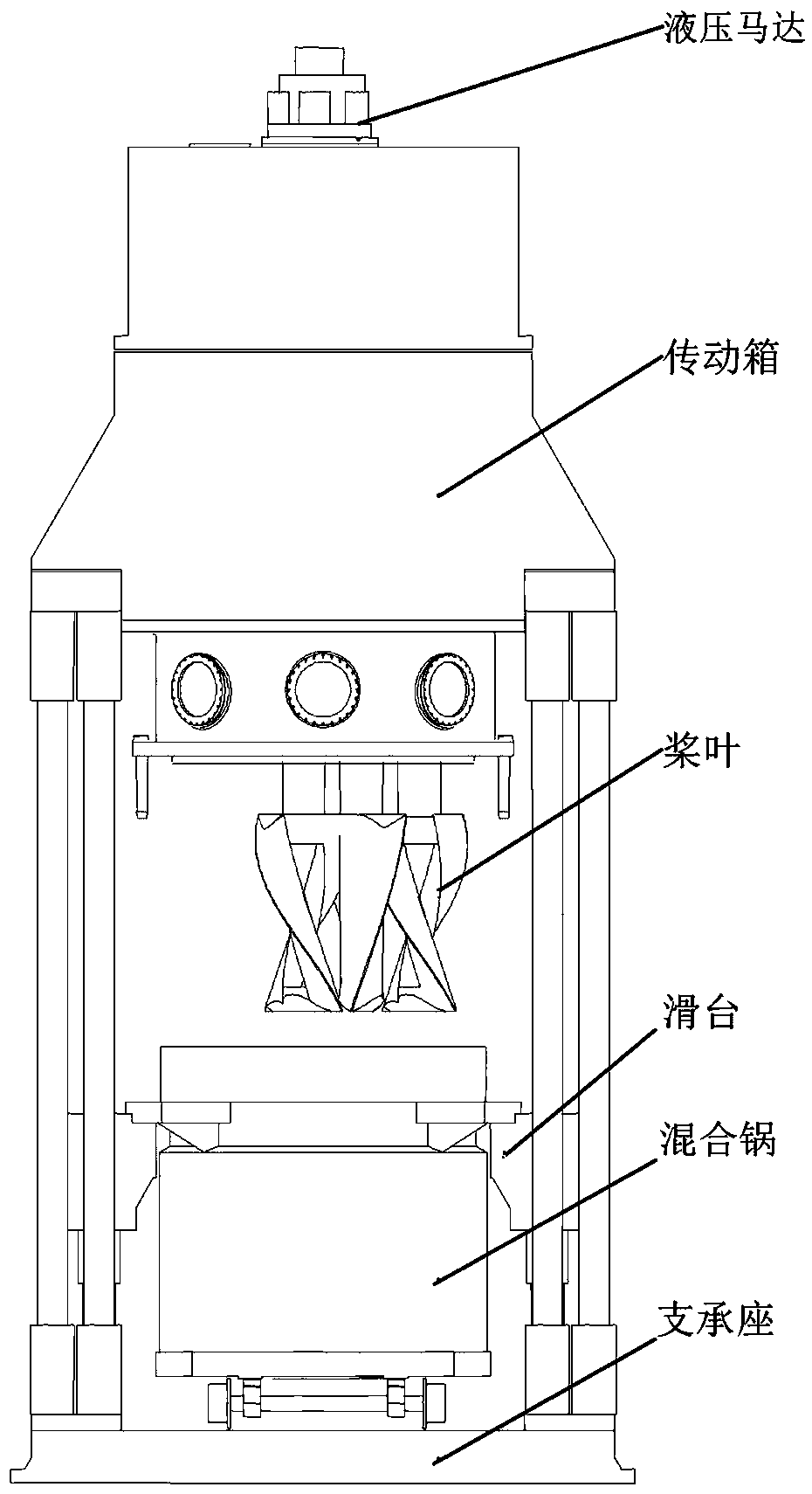
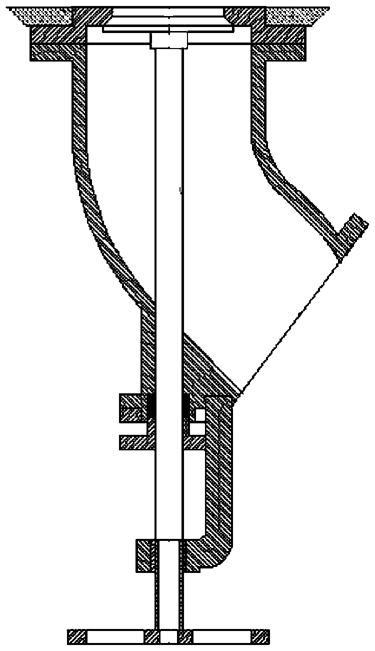
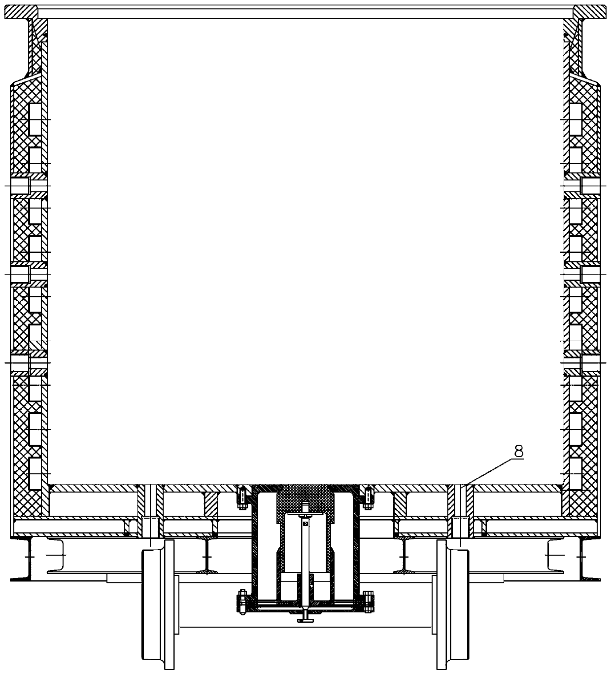
[0032] Such as Figure 3-9 As shown, a mixing pot bottom discharge device includes a mixing pot 8, a valve body 7 is installed at the bottom of the valve body, and the center of the top plate of the valve body is provided with a discharge port 9, which is blocked by a valve core 5 at the discharge port. The lower part of the core is connected to the valve core seat 3 through the ejector rod 4, and a protective cover 1 is provided under the valve core seat 3. The lower edge of the valve body, the edge of the valve core seat and the edge of the protective cover are connected and fixed, and the ejector rod runs through the valve. The back of the core seat is located above the protective cover, and the center of the protective cover is provided with a hole, and fastening bolts are i...


PUM


Abstract

The invention discloses a mixing pot bottom discharge apparatus and an application method thereof. The mixing pot bottom discharge apparatus comprises a mixing pot; a valve is mounted at the bottom ofthe mixing pot; the center of a top plate of the valve is provided with a discharge port; the discharge port is sealed with a valve core; the lower portion of the valve core is connected with a valvecore holder through an ejector rod; a protective cover is arranged below the valve core holder; the lower edge of the valve, the edge of the valve core holder and the edge of a protective cover are fixedly connected; after the ejector rod is passed through the valve core holder, the ejector rod is positioned above the protective cover; the center of the protective cover is provided with a hole; afastening bolt is mounted in the hole to lock the ejector rod. Isolation and connection are separately provided for chemical slurry and inside and outside passages of the mixing pot during mixing andpouring processes; it is ensured that no chemical slurry leaks during the mixing process and mixing pot transport process; the chemical slurry may flow smoothly during pouring. The mixing pot bottomdischarge apparatus helps improve product quality, ensure operational process safety, lower labor intensity for operators and improve working efficiency.

Description

technical field [0001] The invention belongs to the field of solid rocket motor propellant charge, and in particular relates to a bottom discharging device of a mixing pot and a use method thereof. Background technique [0002] The vertical kneader is one of the key production equipment in the production process of rocket engine composite solid propellant charge. Its model specification directly reflects the production capacity and scale of military enterprises. Its structure is as follows: figure 1 As shown, the main part of the equipment is mainly composed of hydraulic motor, transmission box, paddle, slide table, mixing pot, support seat and so on. The mixing pot is an important part of the vertical kneader, and the matching quantity is generally 1 to 3 sets. According to the production process of composite solid propellants, the mixing pots for large vertical kneaders need to complete related operations in three positions: premixing, mixing, and pouring. [0003] The m...

Claims


Application Information

Patent Timeline
Patent Type & Authority Applications(China)
IPC IPC(8): B01F15/02B01F7/18
CPCB01F27/191B01F27/90B01F35/7547B01F2101/503
Inventor 崔峰李方朔邓安华曾广斌鄢柳柳邹德荣左江明陈健
Owner HUBEI SANJIANG AEROSPACE JIANGHE CHEM TECH
Why Eureka
Try Eureka