Steel pipe processing device accurate to position
A technology for steel pipes and working motors, which is applied in positioning devices, metal processing equipment, metal processing machinery parts, etc., can solve the problems of inability to recycle dust, dust environmental pollution, etc., and achieve the effect of facilitating settlement, ensuring stability, and avoiding falling off.
- Summary
- Abstract
- Description
- Claims
- Application Information
AI Technical Summary
Problems solved by technology
Method used
Image
Examples
Embodiment 1
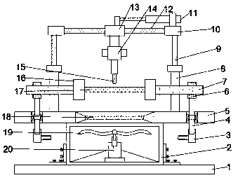
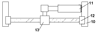
[0019] Depend on figure 1 , 3 As shown, in the embodiment of the present invention, a drilling mechanism includes a support platform 5, a gear 6, a slider 13 and a drill bit 15, two gears 6 are arranged symmetrically on the support platform 5, and the support platform 5 and the gear 6 are fixedly welded. The upper end of the gear 6 is fixedly connected with the column 9 by bolts, the upper end of the column 9 is fixedly welded to the connecting plate 10, a slide bar 12 is arranged between the connecting plates 10, the two ends of the slide bar 12 are fixedly connected with the connecting plate 10 respectively, and the upper end of the slide bar 12 The slide block 13 is sleeved, and the hydraulic cylinder 11 is arranged on the rear side of the slide bar 12, and the hydraulic cylinder 11 is installed on the connecting plate 10, and the telescopic rod of the hydraulic cylinder 11 is welded to the slide block 13;
[0020] The lower part of the slider 13 is fixedly connected with ...
Embodiment 2
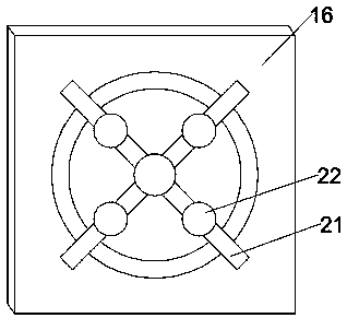
[0024] Depend on Figure 1~3 As shown, in the embodiment of the present invention, a drilling mechanism includes a support platform 5, a gear 6, a slider 13 and a drill bit 15, two gears 6 are arranged symmetrically on the support platform 5, and the support platform 5 and the gear 6 are fixedly welded. The upper end of the gear 6 is fixedly connected with the column 9 by bolts, the upper end of the column 9 is fixedly welded to the connecting plate 10, a slide bar 12 is arranged between the connecting plates 10, the two ends of the slide bar 12 are fixedly connected with the connecting plate 10 respectively, and the upper end of the slide bar 12 The slide block 13 is sleeved, and the hydraulic cylinder 11 is arranged on the rear side of the slide bar 12, and the hydraulic cylinder 11 is installed on the connecting plate 10, and the telescopic rod of the hydraulic cylinder 11 is welded to the slide block 13;
[0025] The lower part of the slider 13 is fixedly connected with th...
Embodiment 3
[0030] Depend on figure 1 As shown, in the embodiment of the present invention, a steel pipe processing device with precise positioning includes the drilling mechanism as described in embodiment 1, and also includes a base 1, an exhaust chamber 2 and a dust collection screen 18, and the base 1 is provided with The exhaust chamber 2, the limit mechanism is arranged on the top of the exhaust chamber 2, and the exhaust chamber 2 and the support platform 5 are fixedly connected by bolts; the top of the exhaust chamber 2 is provided with a dust collection screen 18, and the dust collection screen 18 can Realize the collection and recycling of dust generated during the grinding process, ensuring the cleanliness of the grinding environment;
[0031] The middle position of the bottom surface of the exhaust chamber 2 is fixedly installed with a second working motor 20, a fan blade 19 is arranged above the second working motor 20, the second working motor 20 is welded to the fan blade 1...
PUM
 Abstract
Description
Claims
Application Information
 - R&D
- Intellectual Property
- Life Sciences
- Materials
- Tech Scout
- Unparalleled Data Quality
- Higher Quality Content
- 60% Fewer Hallucinations
Browse by: Latest US Patents, China's latest patents, Technical Efficacy Thesaurus, Application Domain, Technology Topic, Popular Technical Reports.
© 2025 PatSnap. All rights reserved.Legal|Privacy policy|Modern Slavery Act Transparency Statement|Sitemap|About US| Contact US: help@patsnap.com


