Industrial wastewater catalytic oxidation process and equipment

A technology for catalytic oxidation of industrial wastewater, applied in multi-stage water treatment, water/sewage treatment, chemical instruments and methods, etc., can solve the problems of long treatment process, high cost, and long time consumption, so as to improve treatment efficiency and treatment quality , the effect of reducing labor costs

Inactive Publication Date: 2019-04-05
杨朝德
0 Cites 0 Cited by

AI-Extracted Technical Summary

Problems solved by technology

[0003] At present, in the treatment of industrial wastewater, multi-stage treatment is required to meet the discharge standards. The treatment process is long, time-consuming, high cost, and slow, which c...

Method used

In the present embodiment, described electromagnetic flowmeter 11 is fixedly connected with described water pipeline 5, and described electromagnetic flowmeter 11 can monitor the water delivery rate of industrial waste water in described water pipeline 5, and described water pipeline 5 and the slow flow device 12 are sealed and connected by a pipe collar, the slow flow device 12 can reduce the flow rate of industrial wastewater and reduce the impact force, the catalytic stirring motor 13 is connected with the stirring fan blade 14, and the catalytic stirring The motor 13 can drive the stirring blade 14 to rotate.
In the present e...

Abstract

The invention discloses industrial wastewater catalytic oxidation equipment. The equipment includes a wastewater extraction device, an aeration tank and a catalytic pool; the wastewater extraction device is connected to a filter tank; the filter tank is connected to the aeration tank through a water delivery pipeline; a biological filtration grid is disposed on a side edge of the aeration tank; the biological filtration grid communicates with a water outlet pipe; supporting upright columns are disposed below the catalytic pool; a catalyst injection funnel is disposed on the top of the catalytic pool; a catalytic stirring motor is disposed above the catalytic pool; the catalytic stirring motor is connected to a stirring fan blade; and the catalytic pool communicates with an electromagneticflowmeter by a flow slowing device. Beneficial effects are that: a series of assembly line treatment flow for filtration, aeration and oxidation is performed on industrial wastewater, thereby improving treatment efficiency and treatment quality of the industrial wastewater, and at the same time, the labor cost is reduced by automation work.

Application Domain

Treatment involving filtrationMultistage water/sewage treatment +1

Technology Topic

Treatment qualityWater delivery +8

Image

  • Industrial wastewater catalytic oxidation process and equipment
  • Industrial wastewater catalytic oxidation process and equipment
  • Industrial wastewater catalytic oxidation process and equipment

Examples

  • Experimental program(1)

Example Embodiment

[0025] The present invention will be further explained below in conjunction with the drawings:
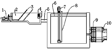
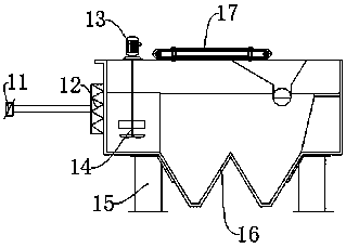
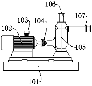
[0026] Such as Figure 1-Figure 3 As shown, a process and equipment for the catalytic oxidation of industrial wastewater includes a wastewater extraction device 1, an aeration tank 6 and a catalytic tank 16. The wastewater extraction device 1 is in communication with a filter tank 2, and the filter tank 2 passes through a water pipe 5. It is connected to the aeration tank 6, a biological filter grid 9 is arranged on the side of the aeration tank 6, and the biological filter grid 9 is in communication with the water outlet pipe 10, and a supporting column 15 is arranged under the catalytic tank 16, A catalyst injection funnel 17 is arranged on the top of the catalytic pool 16, and a catalytic stirring motor 13 is also arranged above the catalytic pool 16. The catalytic stirring motor 13 is connected to the stirring fan blade 14, and the catalytic pool 16 passes through a flow retarder. 12 communicates with the electromagnetic flowmeter 11.
[0027] In this embodiment, the wastewater extraction device 1 is composed of an assembly support platform 101, a pumping motor 102, a work indicator 103, a coupling 104, a pump 105, an inlet pipe 106, and a drainage pipe 107. The assembly support platform 101 Connected to the pumping motor 102 through bolts, the assembly support platform 101 can provide structural support for the pumping motor 102, and the pumping motor 102 is electrically connected to the work indicator light 103, which can The working state of the pumping motor 102 is displayed. The pumping motor 102 is keyed to the coupling 104, and the pumping motor 102 can drive the coupling 104 to rotate.
[0028] In this embodiment, the coupling 104 is in driving connection with the water pump 105, the water pump 105 is in communication with the water inlet pipe 106, and the water pump 105 is in communication with the drain pipe 107.
[0029] In this embodiment, the filter tank 2 is provided with a waste water filter plate 3, and the side wall of the filter tank 2 is provided with a water level monitor 4, and the waste water filter plate 3 can filter out large impurities in industrial waste water. The water level monitor 4 can display the water level inside the filter tank 2 in real time, which is convenient for staff to adjust.
[0030] In this embodiment, an aeration motor 7 is provided above the aeration tank 6, and the aeration motor 7 is in communication with the aeration tube 8. The aeration motor 7 can draw air into the aeration tube 8 In the aeration tank 6, the wastewater is aerated, and the industrial wastewater is oxidized by microorganisms.
[0031] In this embodiment, the rotation speed of the aeration motor 7 is not less than 500 revolutions per minute, and the end of the aeration tube 8 is exposed to the air, which can ensure the quality of the aeration treatment.
[0032] In this embodiment, the electromagnetic flowmeter 11 is fixedly connected to the water pipeline 5, and the electromagnetic flowmeter 11 can monitor the amount of industrial wastewater delivered in the water pipeline 5. The flow retarder 12 is connected in a sealed manner by a pipe clamp. The flow retarder 12 can reduce the flow rate of industrial wastewater and reduce the impact force. The catalytic stirring motor 13 is connected to the stirring fan blade 14 in transmission, and the catalytic stirring motor 13 can Drive the stirring fan 14 to rotate.
[0033] In this embodiment, the supporting column 15 and the catalytic tank 16 are connected by bolt assembly. The supporting column 15 can provide structural support for the catalytic tank 16, and the catalytic tank 16 is fixed to the catalyst injection funnel 17 Connected, the catalyst injection funnel 17 can be used to inject an oxidation catalyst into the catalytic tank 16 to perform oxidation treatment on industrial wastewater.
[0034] In this embodiment, the specific industrial wastewater treatment process is:
[0035] a. Connect the water inlet pipe 106 to the industrial waste water production equipment, and connect the drain pipe 107 to the filter tank 2, and then install the waste water extraction device 1 in a desired position;
[0036] b. The staff starts the pumping motor 102, and the pumping pump 105 is driven by the pumping motor 102 through the coupling 104 to rotate, and industrial waste water is pumped from the production equipment into the filter through the drain pipe 107 Pool 2
[0037] c. The industrial waste water is filtered by the waste water filter plate 3 in the filter tank 2, and then discharged into the aeration tank 6 through the water delivery pipe 5. In the aeration tank 6, The aeration motor 7 draws air into the industrial waste water from the aeration pipe 8 to perform aeration treatment on the industrial waste water, and the duration is not less than three hours;
[0038] d. The aerated industrial wastewater is filtered again by the biological filter grid 9 to remove microorganisms in it, and then discharged into the catalytic tank 16 through the outlet pipe 10, and the electromagnetic flowmeter 11 monitors the flow change at the same time, After that, according to the amount of industrial waste water, the staff put the oxidation catalyst into the catalytic tank 16 from the catalyst injection funnel 17, and the stirring fan 14 stirs the catalytic oxidant and industrial waste water under the driving of the catalytic stirring motor 13 Treatment, so as to oxidize the industrial wastewater, the oxidation time is not less than three hours.

PUM

no PUM

Description & Claims & Application Information

We can also present the details of the Description, Claims and Application information to help users get a comprehensive understanding of the technical details of the patent, such as background art, summary of invention, brief description of drawings, description of embodiments, and other original content. On the other hand, users can also determine the specific scope of protection of the technology through the list of claims; as well as understand the changes in the life cycle of the technology with the presentation of the patent timeline. Login to view more.

Similar technology patents

Boring tool used for machining small-hole-diameter step type round hole inner cavity and provided with replaceable tool head

PendingCN110090975AImprove processing efficiency and processing quality
Owner:SHANXI FENXI HEAVY IND

Side edge grinding device for plate machining

ActiveCN114102316AImprove processing efficiency and processing qualityrelieve pressure
Owner:徐州宏伟木业有限公司

Intelligent path planning device and method for industrial mechanical arm

InactiveCN112643681AGuarantee processing qualityImprove processing efficiency and processing quality
Owner:HUNAN INT ECONOMICS UNIV +1

Threaded rod front fork machining equipment with welding spot firmness test function

PendingCN113399297AImprove detection efficiency and product qualityImprove processing efficiency and processing quality
Owner:成都市惠迈锐智能装备科技有限公司

Automatic winding device

PendingCN114380133AReduce labor costsImprove processing efficiency and processing quality
Owner:科建高分子材料(上海)股份有限公司

Classification and recommendation of technical efficacy words

  • Improve processing efficiency and processing quality
  • Reduce labor costs

Vertical drilling machine

InactiveCN105499635AImprove processing efficiency and processing quality
Owner:NINGBO JINKAI MASCH TOOL CO LTD

Guide ail protecting cover device of end facing machine, guide rail protecting method and end facing machine

InactiveCN106735595AImprove processing efficiency and processing qualityImprove the protective effect
Owner:ZHUZHOU KAIFENG IND

Micro-fluidic chip and preparation method and capture method thereof

ActiveCN110452801Alow costImprove processing efficiency and processing quality
Owner:UNIV OF SCI & TECH OF CHINA

Boring tool used for machining small-hole-diameter step type round hole inner cavity and provided with replaceable tool head

PendingCN110090975AImprove processing efficiency and processing quality
Owner:SHANXI FENXI HEAVY IND

Threaded rod front fork machining equipment with welding spot firmness test function

PendingCN113399297AImprove detection efficiency and product qualityImprove processing efficiency and processing quality
Owner:成都市惠迈锐智能装备科技有限公司
Why Eureka
Try Eureka